Round Punch Automatic Feeding Elevator for High-speed Punch Machine and Control Method

A technology of automatic feeding and high-speed punching, which is applied in the field of elevators and control, can solve the problems of poor reliability and low degree of automation, and achieve the effect of improving matching accuracy, high degree of automation and good stability

Active Publication Date: 2019-01-04
青岛力久电机科技有限公司
View PDF6 Cites 0 Cited by
  • Summary
  • Abstract
  • Description
  • Claims
  • Application Information

AI Technical Summary

Problems solved by technology

[0005] Aiming at the technical problems of low automation and poor reliability of the existing feeding elevator, the present invention provides a high-automation, high-reliability circular punch automatic feeding elevator for high-speed punching machines and a control method

Method used


Image

  • Round Punch Automatic Feeding Elevator for High-speed Punch Machine and Control Method
  • Round Punch Automatic Feeding Elevator for High-speed Punch Machine and Control Method
  • Round Punch Automatic Feeding Elevator for High-speed Punch Machine and Control Method

Examples


Embodiment Construction

[0022] The present invention will be further described below in conjunction with the examples.

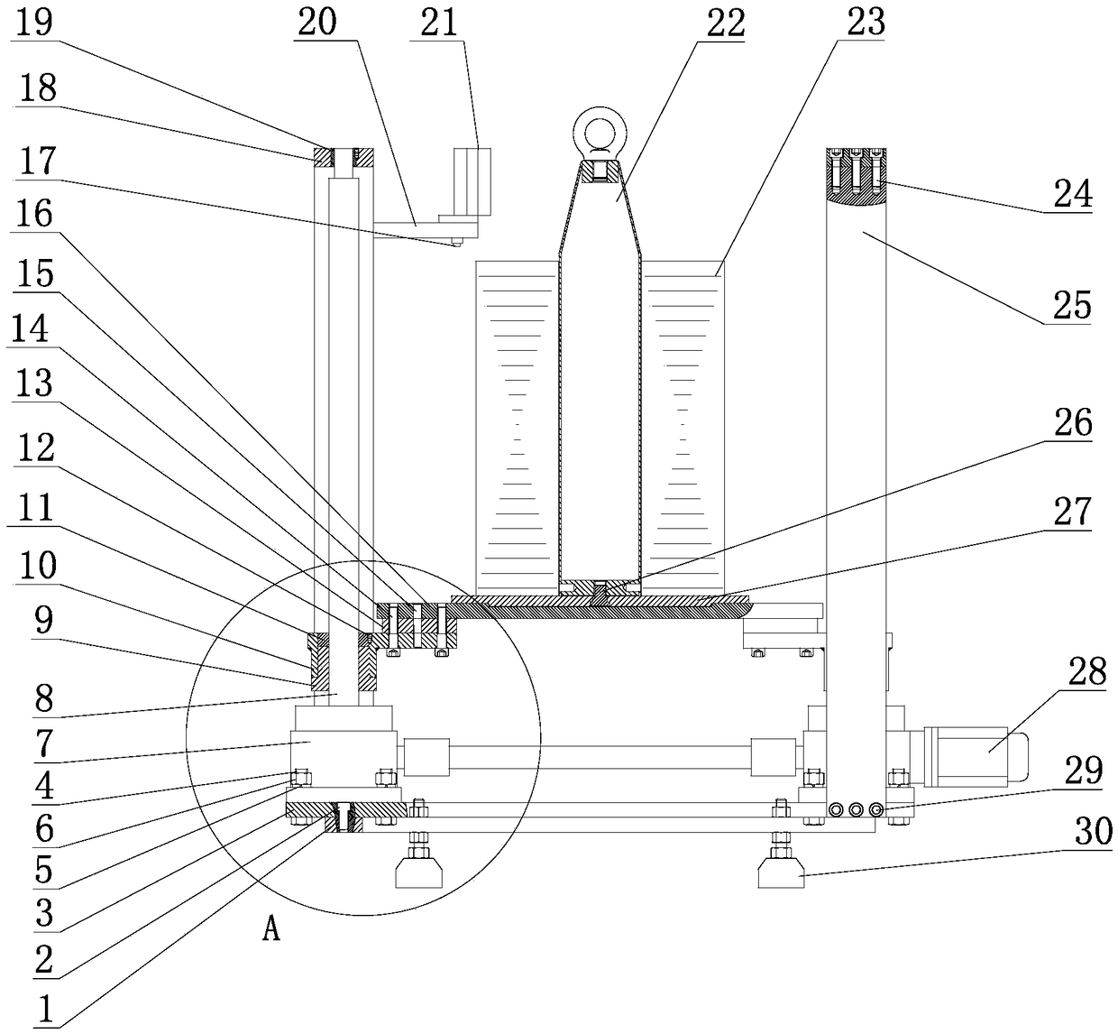
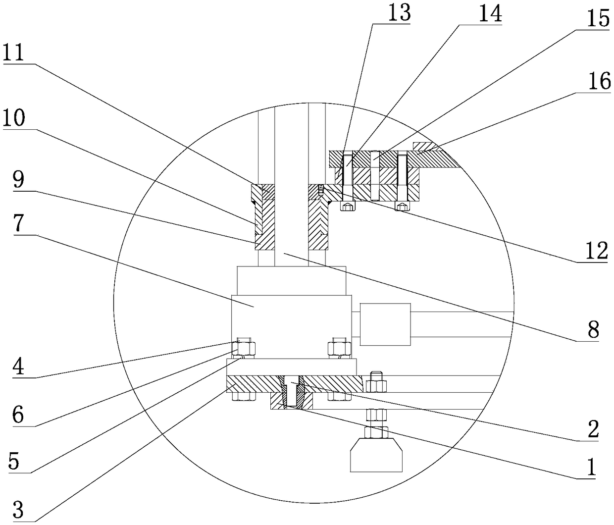
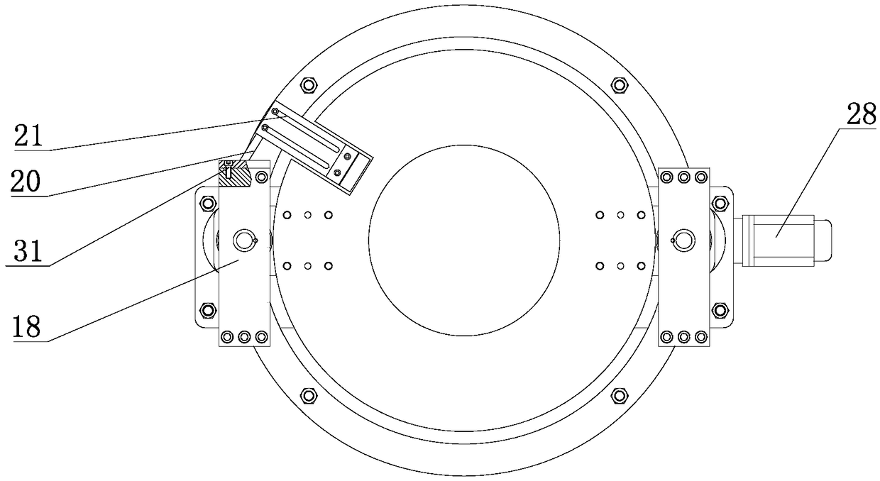
[0023] Such as Figure 1 to Figure 5 As shown, the present invention includes a lifting assembly, a supporting frame, a positioning device, a magnetic divider 21, a position sensor 17 and a CNC control device. The lifting assembly, the magnetic divider 21, and the position sensor 17 are connected to the support frame, the lifting assembly supports a positioning device, and the position sensor 17, the lifting assembly is connected to the CNC control device.

[0024] The upper end of the supporting frame is connected with the magnetic divider adjusting bracket 20 through the fifth fixing bolt 31 , the magnetic divider 21 is connected above the other end of the magnetic divider adjusting bracket 20 , and the position sensor 17 is connected below.

[0025] The supporting frame is provided with a base 1, and the base 1 is circular. Four adjustment feet 30 are fixedly connected to the ...


PUM


Abstract

The invention provides a feeding elevator of high-speed punch by round punching and control method that solves technical problems of low automation and poor reliability of existing feeding elevators. The feeding elevator of high-speed punch by round punching comprises lifting assembly, support frame, positioning device, magnetic separator, position sensor and control device; the lifting assembly, magnetic separator and position sensor are connected with support frame, lifting assembly supports positioning device, and position sensor and lifting assembly are connected with control device. The feeding elevator of high-speed punch by round punching and control method is widely applied in the field of motor punching manufacturing.

Description

technical field [0001] The invention relates to an elevator and a control method, in particular to an automatic feeding elevator and a control method for round punching sheets used in high-speed punching machines. Background technique [0002] Most of the high-speed punching machines use manual feeding, unloading and splitting, and the operator places a punching piece on the positioning plate of the punching machine. After the die work is completed, the operator removes the die from the die and places it separately. Due to the high punching frequency, many punching holes, high noise, and uninterrupted work, the labor intensity is high and the work efficiency is low. It is difficult for the operators to endure such a working environment for a long time. willing to do this kind of work. [0003] The Chinese invention patent application with the application number 201410566047.4 discloses a lifting platform for motor punching piles, including an upper table and a lower table,...

Claims


Application Information

Patent Timeline
Patent Type & Authority Patents(China)
IPC IPC(8): B21D43/10B21D43/00B21D43/02
CPCB21D43/003B21D43/02B21D43/105
Inventor 张成贺付杰钟国奎王毅李班李健伟
Owner 青岛力久电机科技有限公司
Why Eureka
Try Eureka