Combined type suspension system for tracked vehicle
A suspension system and composite technology, which is applied in the field of composite tracked vehicle suspension system, can solve problems such as unsatisfactory vibration damping effect, and achieve the effect of improving driving comfort
- Summary
- Abstract
- Description
- Claims
- Application Information
AI Technical Summary
Problems solved by technology
Method used
Image

Examples
Embodiment Construction
[0022] Below in conjunction with content of the present invention and the example described in accompanying drawing, the present invention will be further described.
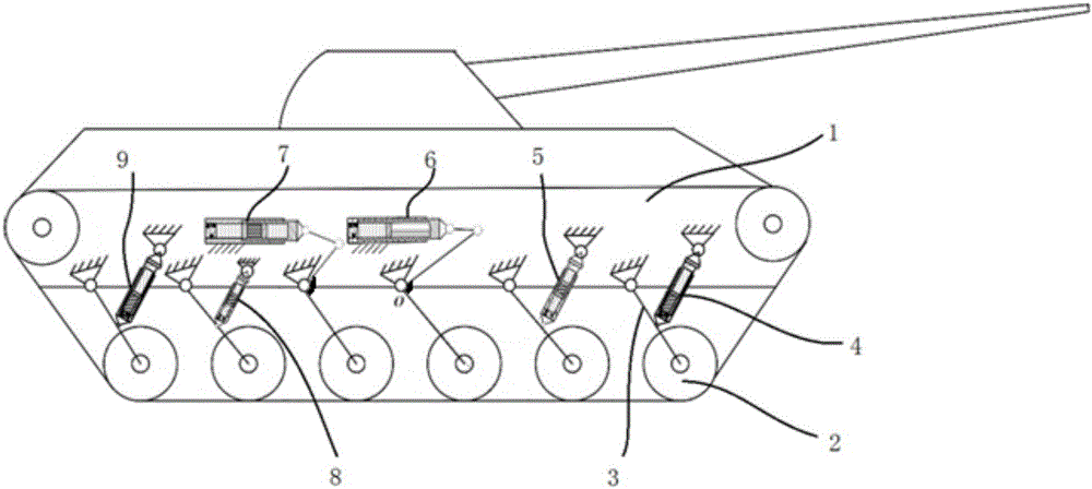
[0023] Such as figure 1 As shown, a compound crawler vehicle suspension system, the vehicle includes a car body 1, twelve road wheels 2 and twelve balance elbows 3, one end of the balance elbow 3 is hinged with the car body 1, and the other end is connected with the car body The load wheel 2 is hinged; it is characterized in that: the structure on both sides of the car body 1 is symmetrical, and the balance elbow 3 on both sides and the car body 1 are sequentially installed with the first single-air chamber oil-pneumatic spring 4 and the first double-air-chamber oil-pneumatic spring 4 from front to rear. Spring 5, the second single air chamber oil-pneumatic spring 6, the second double-air chamber oil-pneumatic spring 7, the third double-air chamber oil-pneumatic spring 8 and the third single-air chamber oil-pneu...
PUM
 Abstract
Description
Claims
Application Information