Guide base

A guide seat and automatic manufacturing technology, which is applied in the direction of textiles and papermaking, cloth feeding mechanism, sewing equipment, etc., can solve the problems of unstable positioning, deviation of sewing stitches, and heavy operating burden of operators, so as to reduce the work burden Effect

Active Publication Date: 2017-01-25
SUZHOU DESIMIER SMART TECH CO LTD
View PDF15 Cites 1 Cited by
  • Summary
  • Abstract
  • Description
  • Claims
  • Application Information

AI Technical Summary

Problems solved by technology

The whole process is relatively complicated, and the operator needs to press the buckle 20 and the belt 10 with his hands during sewing, and move with the sewing base of the equipment, so the positioning is not stable, and it is easy to cause the sewing stitches to deviate, and the overall length of the belt cannot be guaranteed Unified, the operation burden of the operator is relatively large

Method used


Image

  • Guide base
  • Guide base
  • Guide base

Examples


Embodiment Construction

[0027] In order to make it easy to understand the technical means, creative features, goals and effects achieved by the present invention, the following examples are combined with the appended Figures 1 to 5 The guide seat provided by the present invention is described in detail.

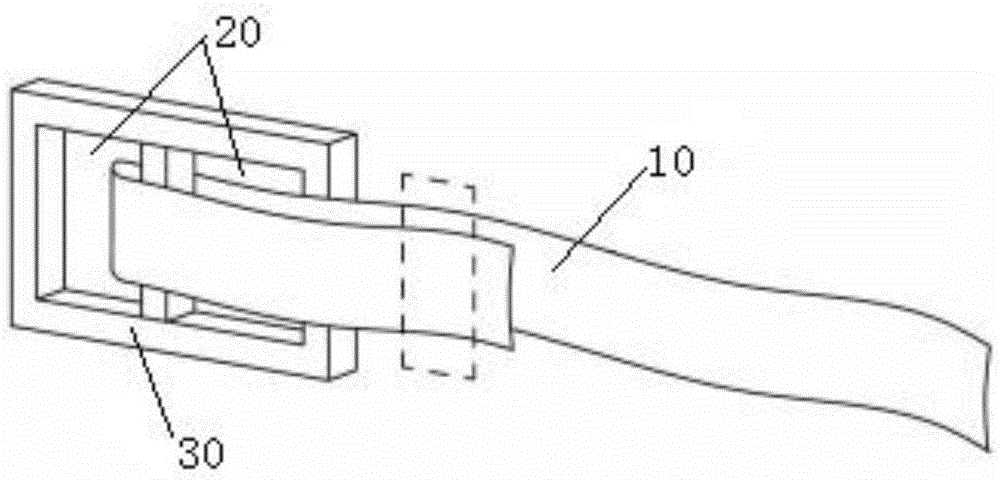
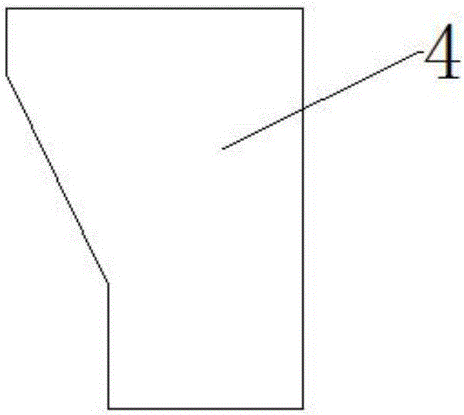
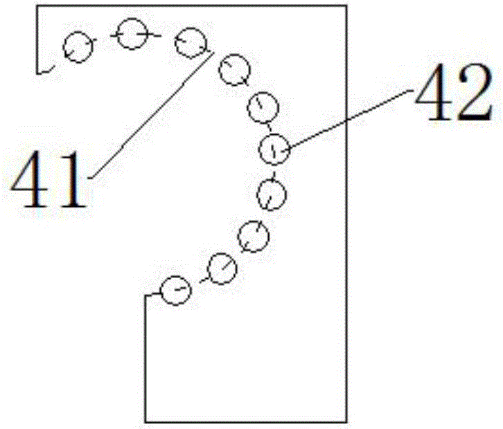
[0028] refer to Figure 2a , is a side view of the appearance structure of an embodiment of a lead seat; combined Figure 2b , is a side view of the internal structure of an embodiment of a guide seat; and Figure 2c , is a bottom view of an embodiment of a guide seat; and Figure 3a and Figure 3b , is a top view and a side view diagram of an embodiment of a guide seat applied to an automatic belt-making machine, and in order to clearly show the structural features of the present invention, part of the structure in the figure is shown in perspective or half-section, and some commonly used structures is omitted, and, Figure 3a and Figure 3b The conveying direction of the belt conveyor 1 sho...


PUM


Abstract

The invention discloses a guide base applied to automatic production machine of belt, wherein the automatic production machine of belt comprises a belt conveyor, a main frame, a belt buckle a conveyor and a control cabinet; the main frame is installed with a sewing mechanism and cutting mechanism, the guide base is provided with arc concave surface in the side towards belt buckle conveyor, the head of the guide belt moves along the arc concave and bends afterwards to form overlapped structure, the surface of arc concave is embedded with multiple rollers, the head of auxiliary belt rotates and bends along the arc concave, an the head of the belt penetrates two ties on the belt buckle after movement along the arc concave and in the process of bending. The technical scheme can automatically and stably finish afterward bending in belt transmission process, penetrate two ties of the belt buckle successively, and form double-layer overlapped structure, which is stable and reliable, and reduces work load of operation personnel.

Description

technical field [0001] The invention relates to the technical field of automatic sewing equipment, in particular to a guide seat. Background technique [0002] The belts on the market are usually sewn by a combination of "Japanese" buckles and belts. Because of their simple structure and individuality, the belts are generally popular among young people and are highly popular. refer to figure 1 As shown in , it is a schematic diagram of the sewing position of the buckle and the belt of the waist belt. In specific manufacturing, it is first necessary to hand-cut the belt 10 approximately to the preset length, and extend one end of the belt 10 into and out of the belt buckle 20. Two lacing holes 30, and then the double-layer overlapping part on the belt 10 is sewn, thereby completing the making of the waist belt. The whole process is relatively complicated, and the operator needs to press the buckle 20 and the belt 10 with his hands during sewing, and move with the sewing bas...

Claims


Application Information

Patent Timeline
Patent Type & Authority Applications(China)
IPC IPC(8): D05B35/08
CPCD05B35/08
Inventor 李德祥
Owner SUZHOU DESIMIER SMART TECH CO LTD
Why Eureka
Try Eureka