Radially engaging coupling system

一种连接机构、啮合的技术,应用在径向啮合连接机构领域,能够解决人力成本超出、耗费大时间和人力等问题,达到结构简单、操作简便、利于推广的效果

Active Publication Date: 2017-01-25
崔侃 +2
View PDF6 Cites 11 Cited by
  • Summary
  • Abstract
  • Description
  • Claims
  • Application Information

AI Technical Summary

Problems solved by technology

This method of assembly and connection is relatively economical in the field of component manufacturing, but it takes a lot of time and manpower in the process of assembly and disassembly
The labor costs of repeating handling of such a simple structure can easily outweigh the initial savings in the structure due to simplicity

Method used


Image

  • Radially engaging coupling system
  • Radially engaging coupling system
  • Radially engaging coupling system

Examples


Embodiment Construction

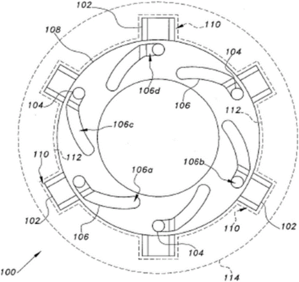
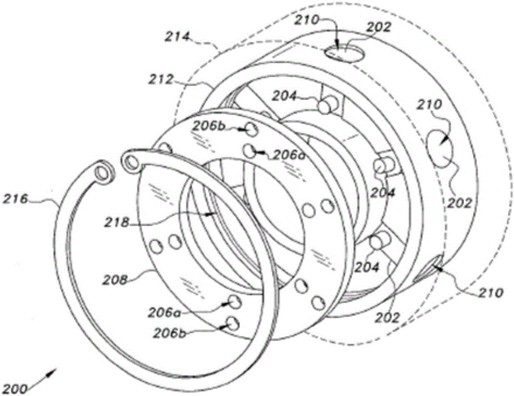
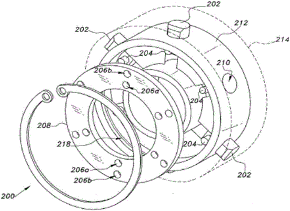
[0036]The radial engagement mechanism of the present invention comprises a number of embodiments, each radial engagement mechanism comprising at least one latch, preferably a plurality of latches; at least one alignment pin extending from each latch; and at least A positioning ring, the positioning ring has at least one inner cut-off positioning point and at least one outer cut-off positioning point, the number of inner cut-off positioning points and outer cut-off positioning points corresponds to the number of pins, and the positioning pin can be adjusted to be set in the positioning The inner cut-off positioning point or the outer cut-off positioning point of the ring, and with the position adjustment of the positioning pin, the radial extension or retraction of the pin can be realized; and a component coaxial with the positioning ring, which is attached to the positioning ring There is at least one bolt socket matching the bolt on the surface of the joint, and the number of ...


PUM


Abstract

The radially engaging coupling system comprises numerous embodiments for connecting two or more concentric components with radially extending or retracting bolts. Most embodiments include a ring having a plurality of Archimedean spiral slotted segments. Each bolt has a pin extending laterally therefrom to engage a corresponding slot in the ring. Rotation of the ring drives the pins and their bolts outward or inward to engage or disengage an outer component. Some embodiments have inwardly or outwardly spaced pin passages in the ring, rather than the spiral slots. The disc may comprise a snap ring. Another embodiment has two axially spaced spirally slotted rings, with a plurality of cylindrical rollers therebetween. Rotation of the rings drives the rollers inward or outward to engage corresponding axial grooves in the inner shaft. By adopting the rotation positioning or the simple mechanical positioning operation of the ring or the disc, the connection or the disengagement of more than two coaxial parts is realized, and therefore the structure is simple, the operation is simple, and the cost is low.

Description

technical field [0001] The present invention relates to mechanical connections and engagement mechanisms, and more particularly to some embodiments of radial engagement mechanisms. Background technique [0002] Interconnecting various rotating components, such as drive shafts that drive driven parts, is required in almost all fields and industries. Probably the most common connection method is to install mating flange parts on the two shafts, and use a certain number of bolts to connect the two shafts together through the flange. This method of assembly and connection is relatively economical in the field of component manufacturing, but it consumes a lot of time and manpower in the process of assembly and disassembly. The labor cost of repeated handling of such a simple structure can easily outweigh the initial savings in the structure due to simplicity. [0003] Therefore, over the past period of time, connection mechanisms between various rotating parts or other parts ha...

Claims


Application Information

Patent Timeline
Patent Type & Authority Applications(China)
IPC IPC(8): F16D1/06
CPCF16D1/06F16D2001/062F16D11/16F16D2023/123F16H25/14F16B21/02F16B37/042
Inventor 崔侃玛格丽特·崔·刘赛米欧·侃·刘
Owner 崔侃
Why Eureka
Try Eureka