Automatic transmission piston simulation experiment device
An automatic transmission and simulation experiment technology, which is applied in the testing of measuring devices, instruments, machines/structural components, etc., can solve problems such as the inability to simulate the working conditions of automatic transmission piston products, and the inability to accurately test the performance requirements of piston products.
- Summary
- Abstract
- Description
- Claims
- Application Information
AI Technical Summary
Problems solved by technology
Method used
Image

Examples
Embodiment Construction
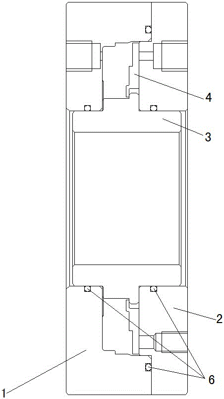
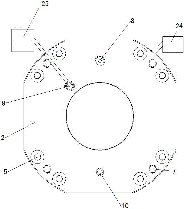
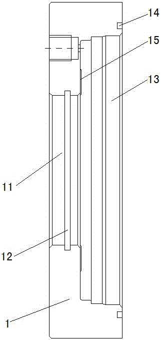
[0018] Such as Figure 1~Figure 10 Shown, a kind of automatic transmission piston emulation experiment device, it comprises test shell 1, test cover 2, installation shaft 3, pad 4, temperature sensor 24, displacement detector 25 and three sealing rings 6; Described test shell 1 A round hole 11 is opened at the center of one of the two opposite end faces, and a sealing ring groove 12 is opened on the inner circumference of the round hole 11 , and the other end face of the two opposite end faces of the test shell 1 A multi-step stepped hole 13 that is coaxial with the circular hole 11 and communicated with it is opened in the center, and a sealing ring groove 2 14 coaxial with the multi-step stepped hole 13 is opened on the other end surface of the test case 1. The test The multi-step step hole 13 in the shell 1 is evenly arranged with a plurality of protrusions 15 on the shoulder end surface adjacent to the round hole 11, and one of the end faces of the test shell 1 is provided...
PUM
 Abstract
Description
Claims
Application Information
 - Generate Ideas
- Intellectual Property
- Life Sciences
- Materials
- Tech Scout
- Unparalleled Data Quality
- Higher Quality Content
- 60% Fewer Hallucinations
Browse by: Latest US Patents, China's latest patents, Technical Efficacy Thesaurus, Application Domain, Technology Topic, Popular Technical Reports.
© 2025 PatSnap. All rights reserved.Legal|Privacy policy|Modern Slavery Act Transparency Statement|Sitemap|About US| Contact US: help@patsnap.com