Test method for specimens suitable for measuring film material constants by ultrasonic resonance spectroscopy

A thin film material and testing method technology, which is applied in the direction of using sound wave/ultrasonic wave/infrasonic wave to analyze solids, etc., can solve problems such as difficult and impossible to measure the film material constant, and achieve the effect of simple structure

Active Publication Date: 2019-10-08
SHANGHAI JIAOTONG UNIV
View PDF3 Cites 0 Cited by
  • Summary
  • Abstract
  • Description
  • Claims
  • Application Information

AI Technical Summary

Problems solved by technology

However, since the thickness of the substrate is much larger than that of the film, material constants related to the thickness direction of the film such as the elastic constant C 33 、C 44 The influence on the eigenfrequency is very small, it is difficult to measure it by this method
[0005] After comparing domestic and foreign patent documents, no patent was found to characterize thin film materials by ultrasonic resonance spectroscopy. In order to measure thin film material constants, Ogi et al. from Osaka University in Japan published a paper Determination of anisotropic elastic constants of superlattice thin films in ActaMaterialia in 2003 Byresonant-ultrasound spectroscopy, the film is grown on the substrate, and the material constant of the diamond film is measured by ultrasonic resonance spectroscopy, but due to the resonance frequency on C 33 、C 44 Insensitive, they cannot measure the material constant C of the film 33 and C 44 , the present invention proposes a solution to corrode small holes in the substrate, and artificially constructs many pairs of C 33 and C 44 Sensitive modality for one-time measurement of a full set of material constants for piezoelectric films

Method used


Image

  • Test method for specimens suitable for measuring film material constants by ultrasonic resonance spectroscopy
  • Test method for specimens suitable for measuring film material constants by ultrasonic resonance spectroscopy
  • Test method for specimens suitable for measuring film material constants by ultrasonic resonance spectroscopy

Examples


Embodiment 1

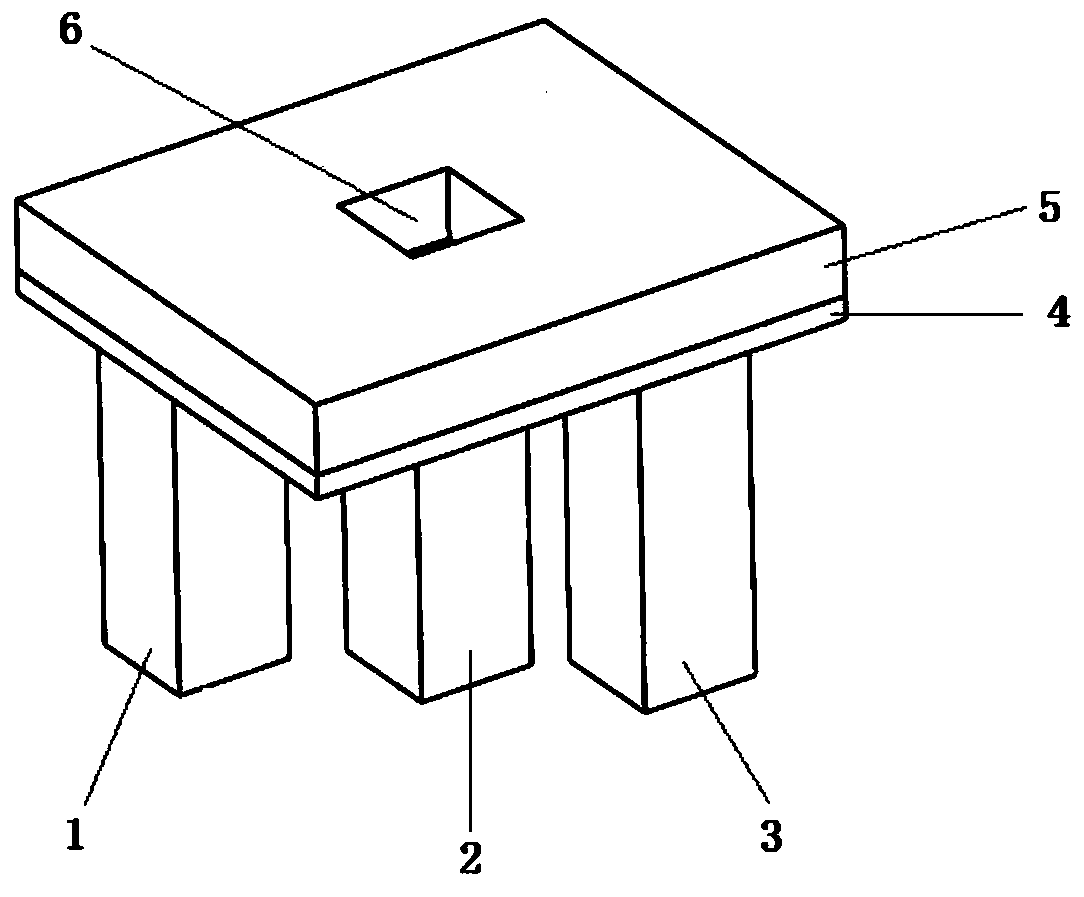
[0044] Such as figure 2 As shown, the acoustic resonance spectroscopy method measures the sample of the material constant of the film, including the substrate, the film and the corrosion hole.

[0045] The film is 20×24mm 2 Sc 0.4 Al 0.6 N film with a thickness of 1 μm. The substrate is SiC with known material constant, and the thickness is 0.5mm. The small hole mentioned is that the bottom surface is 6×5mm 2 A rectangular truss with an angle of 53° between the sides and the bottom, a height of 0.35 mm, and the center coincides with the center of the base.

[0046] The film side of the sample is placed downwards, and is lifted up by three transducers, and the end surface area of ​​the transducers is 5×5mm 2 , in the figure, the receiving transducer is placed at the thin film corresponding to the small hole, because the amplitude here is the largest. The data of the first receiving transducer and the second receiving transducer are fused with each other, which can reduc...

Embodiment 2

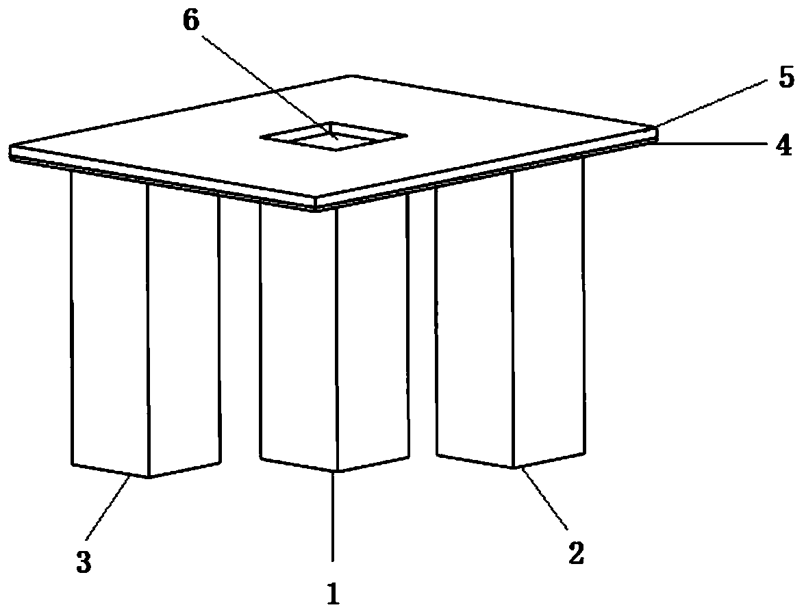
[0050] Such as Figure 4 As shown in Fig. 1, the sample of thin film material constant measured by acoustic resonance spectroscopy includes substrate, thin film and two corrosion holes.

[0051] The film is 20×24mm 2 Sc 0.4 al 0.6 N film with a thickness of 1 μm. The substrate is SiC with known material constant, and the thickness is 0.5mm. There are two small holes, both of which are 5×6mm 2 through-holes, the centers of which are respectively located at the right 1 / 3 of the substrate.

[0052] The sample film is placed downwards and lifted up by three transducers, and the end surface area of ​​the transducers is 5×5mm 2 , in the figure, the receiving transducer is placed at the thin film corresponding to the small hole, because the amplitude here is the largest. The data of the first receiving transducer and the second receiving transducer are fused with each other, which can reduce the influence of a certain transducer modal measurement loss on the whole.

[0053] T...


PUM

PropertyMeasurementUnit
thicknessaaaaaaaaaa
thicknessaaaaaaaaaa
heightaaaaaaaaaa

Abstract

The invention provides a test specimen and a method applicable to testing material constants of a film by the aid of ultrasonic resonance spectrum processes. The test specimen comprises a substrate and the to-be-tested piezoelectric film. The piezoelectric film grows on the substrate. Material constants of the substrate are known, at least one small corrosion hole is formed in the middle of the substrate by means of corrosion, and C33 and C44-sensitive models can be improved by the small corrosion holes. The shapes and the quantities of the small corrosion holes are unlimited, and the distributed locations of the small corrosion holes in the substrate are unlimited. The sides of the piezoelectric film are downwardly placed, and the piezoelectric film is jacked up by three transducers with coplanar tops. The three transducers include a transmitting transducer and two receiving transducers, and the receiving transducers are arranged at the film positioned at the dug holes of the substrate, so that a large quantity of vibration models can be tested. The test specimen and the method have the advantages that the small corrosion holes are formed in the substrate of the test specimen, accordingly, the large quantity of vibration models related to the film can be artificially constructed, and the full set of material constants of the film can be tested by the single test specimen.

Description

technical field [0001] The invention relates to the technical field of piezoelectric thin films, in particular to a sample and a testing method suitable for measuring thin film material constants by ultrasonic resonance spectroscopy. Background technique [0002] Basic material constants are an important basis for evaluating the preparation process and mechanical and electrical properties of materials. The temperature coefficient of basic material constants is an important parameter to accurately describe the properties of materials under high temperature conditions. Without accurate basic material constants and their temperature coefficients, device design, simulation and optimization using this material will be empty talk. [0003] Thin film materials have been widely used in the fields of microacoustic devices, energy harvesting, microelectromechanical systems, structural health monitoring, and intelligent structural control. The development direction of high performance...

Claims


Application Information

Patent Timeline
Patent Type & Authority Patents(China)
IPC IPC(8): G01N29/12
Inventor 韩韬魏书柳张巧珍
Owner SHANGHAI JIAOTONG UNIV
Why Eureka
Try Eureka