Method for calibrating machine tool follow-up laser scanning coordinates on basis of space standard balls

A technology of laser scanning and coordinate calibration, applied in the field of visual measurement, can solve the problems of low calibration efficiency of measurement points and complicated calculation of calibration methods.

Inactive Publication Date: 2017-01-25
DALIAN UNIV OF TECH
View PDF4 Cites 32 Cited by
  • Summary
  • Abstract
  • Description
  • Claims
  • Application Information

AI Technical Summary

Problems solved by technology

This method can also calibrate the laser plane position of the outgoing structured light sensor, but the calculation of

Method used


Image

  • Method for calibrating machine tool follow-up laser scanning coordinates on basis of space standard balls
  • Method for calibrating machine tool follow-up laser scanning coordinates on basis of space standard balls
  • Method for calibrating machine tool follow-up laser scanning coordinates on basis of space standard balls

Examples


Embodiment Construction

[0033] The specific implementation of the present invention will be described in detail below in conjunction with the accompanying drawings and technical solutions.

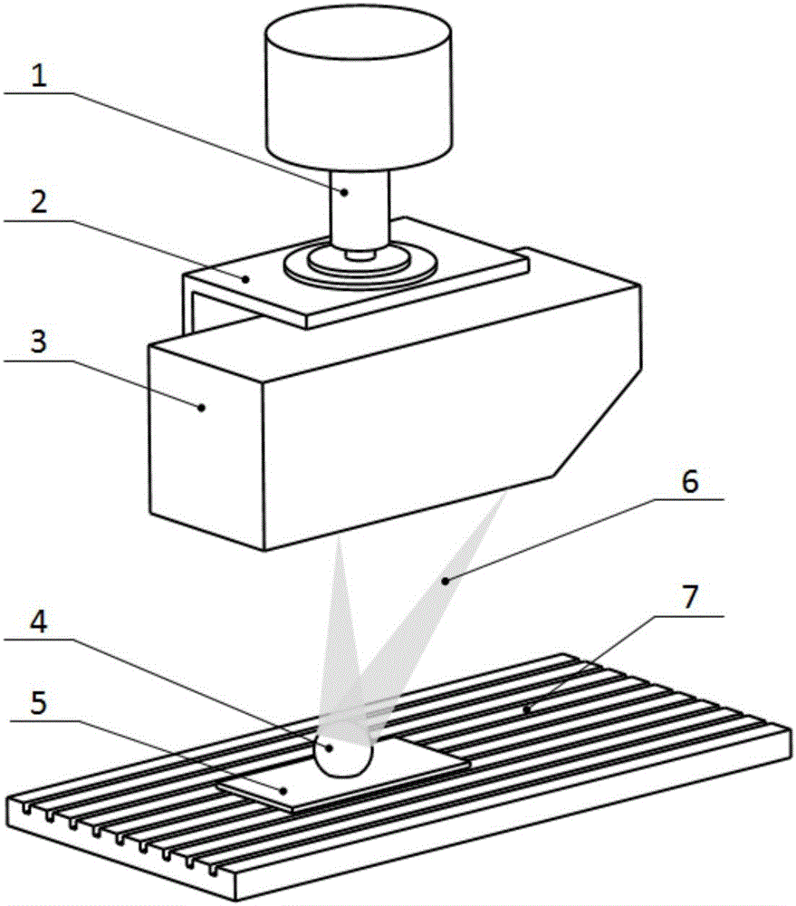
[0034] The line laser measuring sensor 3 selected in this embodiment is the 2420 type measuring instrument of LMI Company, the standard ball 4 selected is a matt ceramic ball with a standard diameter of 10.0134mm, and the machine tool is a Codd CNC machine tool.

[0035] The first step, selecting and arranging the spatial standard sphere

[0036] Relevant preparatory work should be carried out before the calibration of the line laser measurement sensor 3, such as figure 1 As shown, it is necessary to install the laser measurement sensor 3 on the spindle 1 of the CNC machine tool through the sensor connecting plate 2, install the calibration standard ball 4 on the standard ball fixing plate 5, and place it on the workbench 7 of the machine tool, turn on the line laser The measuring sensor 3 adjusts the position o...


PUM


Abstract

The invention discloses methods for calibrating machine tool follow-up laser scanning coordinates on the basis of space standard balls, belongs to the field of vision measurement, and relates to a method for calibrating machine tool follow-up laser scanning coordinates on the basis of space standard balls. The method includes providing third-dimension data for linear laser measurement sensors by movement modules of machine tools; scanning, measuring and fitting circle centers of the space standard balls with known radiuses and unifying data of coordinate systems of the machine tools and linear laser measurement coordinate systems; calibrating default axes of the measurement coordinate systems according to movement of the machine tools and movement of laser planes; calibrating measurement axes; integrally calibrating three-dimensional movement to obtain scale transformation matrixes of the coordinate systems of the machine tools and the measurement coordinate systems. The method has the advantages that the shortcoming that only two-dimensional data can be measured by the traditional laser measurement sensors is overcome, the measurement application ranges of the linear laser measurement sensors can be effectively expanded, and the method has a broad application prospect.

Description

technical field [0001] The invention belongs to the field of visual measurement, and relates to a method for calibrating coordinates of a machine tool following laser scanning based on a space standard sphere. Background technique [0002] With the continuous progress of industrial production, parts measurement has gradually become an indispensable part of production. Various types of measurement problems, including contours, gaps, shapes, and defects, pose great challenges to the accuracy and rapidity of measurement methods. high demands. Among the existing measurement methods, the line laser measurement method has been widely used in industrial production due to its fast, high-precision and non-contact measurement advantages. However, the traditional line laser measurement sensor can only measure two-dimensional data in the laser plane. The measurement sensor itself does not have the function of measuring three-dimensional data, and it cannot be operated when three-dimens...

Claims


Application Information

Patent Timeline
IPC IPC(8): G05B19/408G01B11/00
CPCG01B11/002G05B19/4086
Inventor 刘巍杨帆张洋高鹏兰志广贾振元马建伟
Owner DALIAN UNIV OF TECH
Why Eureka
Try Eureka