Image processing method and electronic equipment

An electronic device and image processing technology, which is applied in image communication, television, electrical components, etc., can solve problems such as blind eyes, poor viewing angle, and inability to adjust, so as to achieve a good image effect

Active Publication Date: 2017-01-25
LENOVO (BEIJING) CO LTD
5 Cites 2 Cited by

AI-Extracted Technical Summary

Problems solved by technology

[0003] However, since the camera is usually placed on the upper part of the electronic device, and the image frame is displayed on the display unit in the middle of the electronic device, this difference in viewing angle causes such a contradiction that if the user ob...

Abstract

The invention discloses an image processing method and electronic equipment. The image processing method is applied in the electronic equipment comprising an image acquiring unit and includes: acquiring a first image of a photographed object in a first state through the image acquiring unit, wherein a first area of the photographed object in the first state directly faces the image acquiring unit; acquiring a second image of the photographed object through the image acquiring unit; extracting a first sub image of a first area in the first image and a second sub image of the first area in the second image to generate a third sub image; using the third sub image to replace the second sub image in the second image to generate a third image of the photographed image.

Application Domain

Technology Topic

Image

  • Image processing method and electronic equipment
  • Image processing method and electronic equipment
  • Image processing method and electronic equipment

Examples

  • Experimental program(3)

Example

[0022]
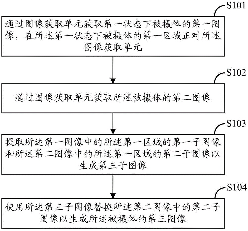
[0023] The following will combine figure 1 with Figure 2a-2d The image processing method according to the first embodiment of the present invention will be described together. figure 1 It is a flowchart illustrating the image processing method according to the first embodiment of the present invention. Figure 2a-2c It is an effect diagram illustrating the image processing method according to the first embodiment of the present invention. The image processing method 100 according to the first embodiment of the present invention is applied to an electronic device, and such an electronic device may be any electronic device as long as the electronic device has an image capturing unit such as a camera. For example, the electronic device may be a desktop computer, a notebook computer, a tablet computer, a smart phone, and so on.
[0024] In addition, in this embodiment, the image processing method according to the first embodiment of the present invention will be described assuming that the electronic device is a smart phone and the user uses the smart phone to take a selfie.
[0025] The image processing method 100 according to the first embodiment of the present invention includes:
[0026] Step S101: Acquire a first image of a subject in a first state by an image acquisition unit, and the first area of ​​the subject in the first state is facing the image acquisition unit;
[0027] Step S102: Acquire a second image of the subject through an image acquisition unit;
[0028] Step S103: extracting a first sub-image of the first area in the first image and a second sub-image of the first area in the second image to generate a third sub-image; and
[0029] Step S104: Use the third sub-image to replace the second sub-image in the second image to generate a third image of the subject.
[0030] As everyone knows, the camera of a smart phone is usually set on the top of the phone. Therefore, when the user is taking a self-portrait, if the user stares at the display screen to determine the composition and observe his own expression, he does not see the camera because his eyes are staring at the screen, which results in the user's eyes in the captured image being apathetic. On the other hand, if the user is staring at the camera, he cannot see his own expression, composition, etc. to make adjustments.
[0031] Therefore, in the image processing method according to the first embodiment of the present invention, in step S101, the first image of the subject in the first state is acquired through the image acquisition unit of the electronic device (such as a camera). In a state, the first area of ​​the subject is facing the image acquisition unit. That is to say, in step S101, when the user starts to take a self-portrait, the user first stares at the camera, and takes a picture of the first image with the eyes looking at the camera, that is, the first image with the gods in the eyes. For example, you can get Figure 2a Picture shown.
[0032] Then, in step S102, a second image of the subject is acquired by an image acquisition unit. That is to say, in this step S102, the user can adjust different postures to take pictures while keeping the posture as much as possible (the posture of the head is generally unchanged) to obtain the second image. For example, you can get Figure 2b Picture shown.
[0033] It should be noted that, in this embodiment, for example, in the case where the user takes a selfie to take a photo, the first image may be acquired by the image acquisition unit at the first time point, and the first image may be acquired at the first time point. The second image is acquired by the image acquisition unit at a different second time point. That is, the first image and the second image can be acquired sequentially.
[0034] Of course, as well known to those skilled in the art, the order of acquiring the first image and the second image is not limited to this, and the second image may be acquired first, and then the first image may be acquired.
[0035] Then, in step S103, a first sub-image of the first area in the first image and a second sub-image of the first area in the second image are extracted to generate a third sub-image.
[0036] Specifically, in this step S103, an image processing algorithm may be used to extract the first sub-image related to the eye area from the first image. In addition, an image processing algorithm may be used to extract a second sub-image related to the eye area from the second image. Then, a third sub image is generated based on the first sub image and the second sub image. For example, such as Figure 2c The image of the eye area shown. Since the third sub-image is taken with the eyes fixed on the camera, the eyes are energized.
[0037] That is, based on the sub-image of the eye area acquired from the first image and the sub-image of the eye area acquired from the second image, the third sub-image regarding the eye area is generated. The third sub-image is, for example, a sub-image of an eye area with a strong eye.
[0038] In this embodiment, for example, the first sub-image may be directly used as the third sub-image.
[0039] In another embodiment, the first sub-image and the second sub-image may be merged to generate the third sub-image through image fusion technology.
[0040] Then, in step S104, the third sub-image may be used to replace the second sub-image in the second image to generate a third image of the subject.
[0041] That is to say, by replacing the second sub-image with godless eyes in the second image with the third sub-image with godly eyes, an image with godly eyes and satisfactory composition and posture can be generated. For example, such as Figure 2d Picture shown.
[0042] It should be noted that in the case of multiple users taking selfies together, the first images of multiple users can be acquired, that is, multiple users staring at the camera at the same time to take the first image.
[0043] Then, in a subsequent step, the user operating the electronic device for shooting stares at the screen of the electronic device to determine the composition and guide other users' posture adjustments, and other users continue to stare at the camera to capture the second image. Then the sub-image extraction and image synthesis are performed in the same way as above.
[0044] Therefore, according to the image processing method of the first embodiment of the present invention, the user can obtain a better image.

Example

[0045]
[0046] The following will combine image 3 with Figure 4a-4d The image processing method according to the second embodiment of the present invention will be described together. image 3 It is a flowchart illustrating the image processing method according to the second embodiment of the present invention. Figure 4a-4c It is an effect diagram illustrating the image processing method according to the second embodiment of the present invention. The image processing method 200 according to the second embodiment of the present invention is applied to an electronic device, and such an electronic device may be any electronic device as long as the electronic device has an image capturing unit such as a camera. For example, the electronic device may be a desktop computer, a notebook computer, a tablet computer, a smart phone, and so on.
[0047] In addition, in this embodiment, it will be assumed that the electronic device is a notebook computer with a first camera subunit and a second camera subunit (ie, two cameras), and the user uses the notebook computer to make a video call. Invented the second embodiment of the image processing method.
[0048] In this embodiment, the first camera subunit and the second camera subunit are, for example, arranged on two opposite sides of the electronic device. For example, the first camera is arranged above the display screen of the notebook computer, and the second camera is arranged below the display unit of the notebook computer. In this embodiment, the first camera and the second camera may be aligned in the vertical direction, for example.
[0049] In another embodiment, the first camera subunit and the second camera subunit are arranged to have a predetermined offset distance.
[0050] The image processing method 200 according to the second embodiment of the present invention includes:
[0051] Step S201: Acquire a first image of a subject in a first state through the first camera subunit, and the first area of ​​the subject in the first state is facing the first camera subunit;
[0052] Step S202: Acquire the second image through the second camera subunit at the same time point;
[0053] Step S203: extracting a first sub-image of the first area in the first image and a second sub-image of the first area in the second image to generate a third sub-image; and
[0054] Step S204: Use the third sub-image to replace the second sub-image in the second image to generate a third image of the subject.
[0055] As everyone knows, when a user is making a video call, he does not see the camera because his eyes are staring at the screen, which results in the user's eyes being apathetic in the captured image. On the other hand, if the user is staring at the camera, he cannot see his own expression, composition, etc. to make adjustments.
[0056] Therefore, in the image processing method according to the second embodiment of the present invention, because two cameras are provided, in step S201, the first image of the subject in the first state can be acquired through the first camera of the electronic device, In the first state, the first area of ​​the subject is facing the first camera. That is to say, in step S201, when the user starts a video call, the user stares at the first camera set below to obtain the first image with energetic eyes. For example, you can get Figure 4a Picture shown.
[0057] Then, in step S202, the second image is acquired by the second camera subunit at the same time point. That is, in this step S202, the second camera acquires the second image of the user at the same time point. For example, you can get Figure 4b Picture shown.
[0058] Then, in step S203, a first sub-image of the first area in the first image and a second sub-image of the first area in the second image are extracted to generate a third sub-image.
[0059] Specifically, in this step S203, an image processing algorithm may be used to extract the first sub-image about the eye area from the first image. For example, such as Figure 4c The image of the eye area shown is additionally. At the same time, an image processing algorithm can be used to extract a second sub-image about the eye area from the second image. Such as Figure 4d The image of the eye area shown. Then, a third sub image is generated based on the first sub image and the second sub image. Because the third sub-image is taken with the eyes fixed on the first camera, the eyes are energizing.
[0060] That is, based on the sub-image of the eye area acquired from the first image and the sub-image of the eye area acquired from the second image, the third sub-image regarding the eye area is generated. The third sub-image is, for example, a sub-image of an eye area with a strong eye.
[0061] In this embodiment, for example, the first sub-image may be directly used as the third sub-image.
[0062] In another embodiment, the first sub-image and the second sub-image may be merged to generate the third sub-image through image fusion technology.
[0063] Then, in step S204, the third sub-image may be used to replace the second sub-image in the second image to generate a third image of the subject.
[0064] In one embodiment, because the eyes are facing the camera, there will be obvious reflective points in the eyes. Therefore, reflective points can also be added to the pupils of the eyes in the third sub-image.
[0065] For example, the reflective point can be increased in the middle or upper 1/3 of the pupil. The size of the flash point can be set to 2% of the pupil area, the color is white, and the edge is softened with 01 point. This can make the synthesized image better.
[0066] That is to say, by replacing the second sub-image with godless eyes in the second image with the third sub-image with godly eyes, an image with godly eyes and satisfactory composition and posture can be generated. For example, such as Figure 4e Picture shown.
[0067] Therefore, according to the image processing method of the second embodiment of the present invention, the user can obtain a better video call image.

Example

[0068]
[0069] Refer to below Figure 5 The electronic device 500 according to the fifth embodiment of the present invention is described.
[0070] The electronic device 500 includes:
[0071] The image acquisition unit 501 is configured to acquire an image of a subject;
[0072] The control unit 502 is configured to control the image acquisition unit to acquire a first image of the subject in the first state, and in the first state, the first area of ​​the subject faces the image acquisition unit and controls the image An acquiring unit acquires a second image of the subject;
[0073] The sub-image extraction unit 503 is configured to extract a first sub-image of the first area in the first image and a second sub-image of the first area in the second image to generate a third sub-image ;as well as
[0074] The image synthesis unit 504 is configured to replace the second sub-image in the second image with the third sub-image to generate a third image of the subject.
[0075] Preferably, the first image is acquired by the image acquisition unit 501 at a first time point, and the second image is acquired by the image acquisition unit at a second time point different from the first time point.
[0076] Preferably, extracting a first sub-image of the first area in the first image and a second sub-image of the first area in the second image to generate a third sub-image further includes:
[0077] The first sub-image is directly used as the third sub-image.
[0078] Preferably, the sub-image extraction unit 502 is further configured to perform image fusion processing on the first sub-image and the second sub-image to generate the third sub-image.
[0079] Preferably, the image acquisition unit 501 includes a first camera subunit and a second camera subunit, and
[0080] At the same time point, the first image is acquired by the first camera subunit, and the second image is acquired by the second camera subunit.
[0081] Preferably, the first camera subunit and the second camera subunit are arranged on two opposite sides of the electronic device.
[0082] Preferably, the first camera subunit and the second camera subunit are arranged to have a predetermined offset distance.
[0083] Preferably, the first area is the user's eyes.
[0084] Therefore, the image processing method and the electronic device according to the embodiments of the present invention enable users to obtain better images.
[0085] It should be noted that when the electronic device according to each embodiment is illustrated, only its functional units are shown, and the connection relationship of each functional unit is not described in detail. Those skilled in the art can understand that each functional unit can pass through a bus. , Internal connecting wires, etc. are properly connected, and such connections are well known to those skilled in the art.

PUM

no PUM

Description & Claims & Application Information

We can also present the details of the Description, Claims and Application information to help users get a comprehensive understanding of the technical details of the patent, such as background art, summary of invention, brief description of drawings, description of embodiments, and other original content. On the other hand, users can also determine the specific scope of protection of the technology through the list of claims; as well as understand the changes in the life cycle of the technology with the presentation of the patent timeline. Login to view more.

Similar technology patents

Curve determination method, device and equipment

PendingCN114245002AGood imageUnsmoothTelevision system detailsColor television detailsOphthalmologyZoom lens
Owner:HANGZHOU HIKVISION DIGITAL TECH

Ultrasonic imaging system and imaging method

Owner:THE HONG KONG POLYTECHNIC UNIV

Classification and recommendation of technical efficacy words

Why Eureka
Try Eureka