Motor chip punching device and method

A stamping device and chip technology, which is applied in the field of motor parts manufacturing, can solve the problem that the flatness of the motor chip cannot meet the requirements, and achieve the effect of more attractive appearance and good flatness of the product

Inactive Publication Date: 2017-02-01
SHENZHEN HORENTOP TECH
View PDF8 Cites 6 Cited by
  • Summary
  • Abstract
  • Description
  • Claims
  • Application Information

AI Technical Summary

Problems solved by technology

[0003] Based on this, it is necessary to address the problem that the flatness of the motor chip is difficult to mee

Method used


Image

  • Motor chip punching device and method
  • Motor chip punching device and method
  • Motor chip punching device and method

Examples


Embodiment Construction

[0020] The motor chip stamping device provided by the present invention can be used to form stator cores, rotor cores and other chips used in motors.

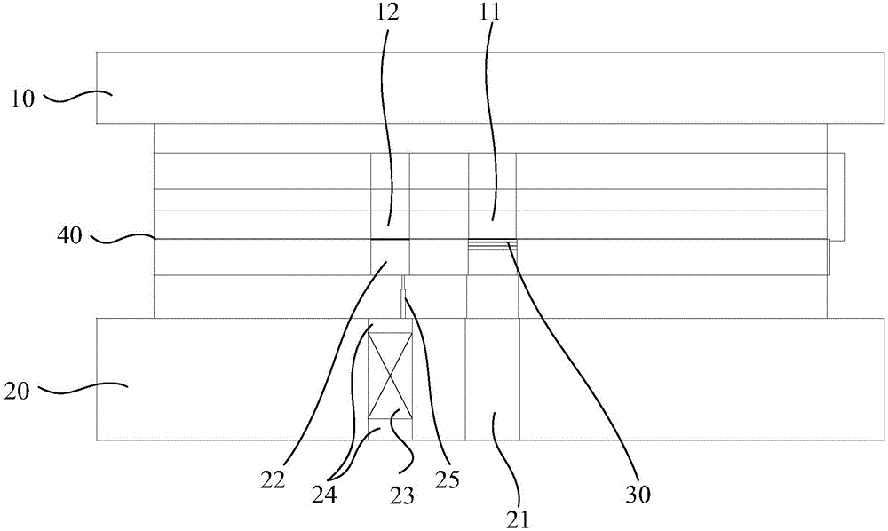
[0021] Such as figure 1 As shown, a motor chip stamping device provided by an embodiment includes an upper die 10 and a correspondingly arranged lower die 20, the upper die 10 is provided with a first punch 11, and the lower die 20 is provided with a corresponding first punch 11. There is a corresponding first concave mold 21 , and the first convex mold 11 and the first concave mold 21 cooperate with the die-cut strip 40 to form the motor chip 30 .

[0022] The first punch 11 can be the punch of the blanking strip 40, and the profile of the punch is designed according to the molding process of the motor chip 30. In this embodiment, the first punch 11 is the last process of forming the motor chip 30. Therefore, the corresponding portion of the material strip 40 is completely punched to be separated from the material strip 40 , ...


PUM


Abstract

The invention relates to a motor chip punching device which comprises an upper die and a lower die, and further comprises a second male die and a floating roof, wherein the lower die is correspondingly arranged with the upper die; a first male die is arranged on the upper die; a first female die corresponding to the first male die is arranged on the lower die; the first male die and the first female die are matched for punching of a material belt, thereby forming a motor chip; the second male die is arranged on the upper die; the floating roof is arranged on the lower die and corresponds to the second male die; the second male die is used for partially punching the material belt along the thickness direction of the material belt; the floating roof is used for being propped against the material belt, so as to correct the flatness of the material belt when the material belt is partially punched by the second male die; and the first male die is used for punching the material belt again after the material belt is partially punched by the second male die, thereby forming the motor chip. The invention further provides a motor chip punching method. A step-by-step punching mode is adopted, so that the flatness of the motor chip can be corrected during step-by-step punching, and then the motor chip being higher in flatness can be obtained. Meanwhile, the shearing surface of the motor chip becomes brighter, so that the appearance attraction of the motor chip can be further improved.

Description

technical field [0001] The invention relates to the field of manufacturing motor components, in particular to a stamping device and method for a motor chip. Background technique [0002] Motor chips, such as rotor cores, stator cores, etc., are generally punched into pieces from materials. Some chips are thinner, eg, 1mm thick. When these chips are stamped and formed, due to factors such as the precision of the mold and the strength of the strip, the flatness of the formed chips is poor, which cannot meet the requirements of some chips that require high flatness. Contents of the invention [0003] Based on this, it is necessary to provide a stamping device and method capable of producing a motor chip with a higher flatness for the problem that the flatness of the motor chip cannot meet the requirements. [0004] A stamping device for a motor chip, comprising an upper die and a correspondingly arranged lower die, the upper die is provided with a first punch, and the lower...

Claims


Application Information

Patent Timeline
IPC IPC(8): B21D28/14B21D28/02B21D28/04
Inventor 刘振德张强张云熊春英郭小军
Owner SHENZHEN HORENTOP TECH
Why Eureka
Try Eureka