

Cutting device of optical part cutting machine
A technology for optical parts and cutting devices, applied in fine working devices, stone processing equipment, manufacturing tools, etc., can solve problems such as inability to achieve high-precision cutting dimensions, affecting the surface finish of optical parts, and inability to achieve ideal parts fixation, etc. The effect of saving mounting parts, improving dimensional accuracy and good flatness
- Summary
- Abstract
- Description
- Claims
- Application Information
AI Technical Summary
Problems solved by technology
Method used
Image

Examples
Embodiment Construction
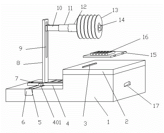
[0020] Below in conjunction with accompanying drawing, the present invention is further described
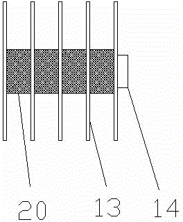
[0021] As shown in Figures 1, 2, and 3, the system mainly includes base 1, base plate 2, reference block 3, horizontal frame 4, longitudinal rail groove 5, longitudinal frame 6, horizontal rail groove 7, vertical column 8, vertical rail groove 9. Connecting rod 10, tool holder 11, rotating shaft 12, tool 13, fastening holder 14, backing plate 15, workpiece 16, add / degauss button 17, electromagnet 18, cable 19 and flange 20, etc.
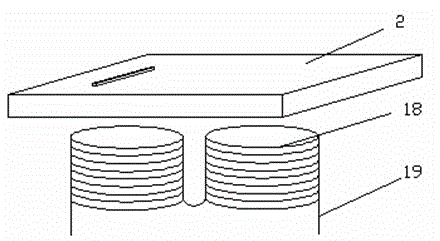
[0022] In this example, as shown in Figure 2, both the base plate and the backing plate are made of iron plates, and an electromagnet is installed under the base plate. And the backing plate placed on the base plate is sucked tightly to fix the cutting workpiece. The fastening performance is good, and there will be no deviation due to vibration during the cutting process, which can ensure the accurate size of the cutting workpiece.
[0023] As shown i...
PUM
 Abstract
Description
Claims
Application Information