

Optical element and manufacturing method thereof
A technology of optical components and manufacturing methods, applied in the direction of diffusion components, etc., can solve the problems affecting the product yield of optical components, affecting the surface flatness of forming rollers, etc., achieving good flatness, high precision, and improving product yield.
- Summary
- Abstract
- Description
- Claims
- Application Information
AI Technical Summary
Problems solved by technology
Method used
Image

Examples
Embodiment Construction
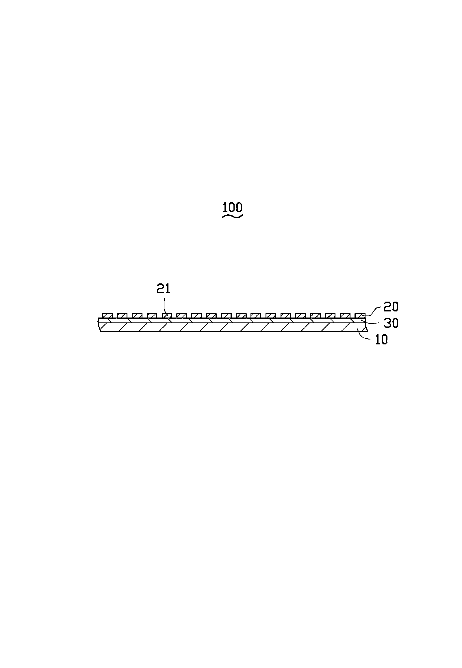
[0012] see figure 1 , is an optical element 100 provided by an embodiment of the present invention, which includes a transparent substrate 10 , a transparent optical film 20 and a transparent adhesive layer 30 . The surface of the optical film 20 facing away from the substrate 10 has a microstructure pattern 21 .
[0013] The material of the base material 10 is an organic polymer, and the optical film 20 is obtained by curing UV glue including monomers of the organic polymer. In this embodiment, the material of the substrate 10 is polymethylmethacrylate (PMMA), which is referred to as acrylic resin for short. The optical film 20 is formed by curing UV glue containing PMMA monomer (PMMA UV glue for short). Because PMMA UV glue includes PMMA monomers and photoinitiators, the photoinitiators generate active free radicals or cations after absorbing ultraviolet light under the irradiation of ultraviolet rays, triggering the chemical reactions of polymerization, crosslinking and b...
PUM
 Abstract
Description
Claims
Application Information