Ceiling fan cleaning device and automatic ceiling fan cleaning method

A technology for cleaning devices and ceiling fans, which is applied to household cleaning devices, cleaning equipment, components of pumping devices for elastic fluids, etc. Long, easy to use, stable and reliable locking effect

Inactive Publication Date: 2017-02-01
YANGTZE NORMAL UNIVERSITY
View PDF13 Cites 4 Cited by
  • Summary
  • Abstract
  • Description
  • Claims
  • Application Information

AI Technical Summary

Problems solved by technology

[0004] The ceiling fan can rely on centrifugal force to clean the fan blade dust; but there are still the following defects: 1. In the ceiling fan cleaning device, the electromagnet is arranged in the middle of the spring, and the electromagnet is directly attracted to the spring to realize the cleaning of the cleaning body. The locking effect is poor. When the fan is working normally, the cleaning body is easily thrown out, which affects the normal use of the ceiling fan and reduces the service life of the device.
2. When the device is working, it is necessary to set a special cleaning gear switch, and the control method of the ceiling fan needs to be changed. The control structure is complicated and manual operation is required for cleaning, which cannot achieve complete automatic control. Advocated low-carbon environmental protection concept

Method used


Image

  • Ceiling fan cleaning device and automatic ceiling fan cleaning method
  • Ceiling fan cleaning device and automatic ceiling fan cleaning method

Examples


Embodiment Construction

[0026] The present invention will be further described in detail below in conjunction with the accompanying drawings.

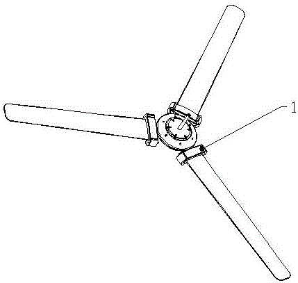
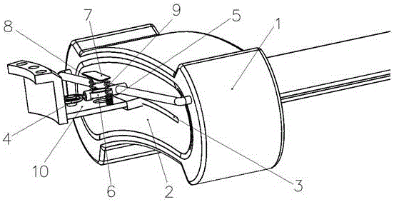
[0027] During specific implementation: if figure 1 , figure 2 As shown, a ceiling fan cleaning device includes a blade cleaning block and a blade cleaning block control device, the blade cleaning block is sleeved on the blade 10, and the blade cleaning block control device includes an elastic reset member 4 and an electromagnet control mechanism One end of the elastic resetting member 4 is fixed on the inner end of the blade 10, and the other end is fixedly connected to the blade cleaning block. The electromagnet control mechanism includes an electromagnet 5, which is fixed on the inner end of the blade 10, and the electromagnet 5 After energizing, the blade cleaning block can be locked on the inner end of the blade 10 so that it is in a non-working state. After the electromagnet 5 is powered off, the locking of the blade cleaning block can be canceled. In ...


PUM


Abstract

The invention discloses a ceiling fan cleaning device. The ceiling fan cleaning device comprises a blade cleaning block and a blade cleaning block control device which comprises an elastic reset component and an electromagnet, the blade cleaning block is provided with a limiting hole, and when the blade cleaning block is in a non-operating state, a limiting block is correspondingly arranged in the depth direction of the limiting hole; the ceiling fan cleaning device further comprises a reset spring connected between the electromagnet and the limiting block, the electromagnet can attract the limiting block to make the limiting block embedded in the limiting hole after being energized, and after the electromagnet is deenergized, the limiting block can get out of the limiting hole under the action of reset springs. The invention further discloses an automatic ceiling fan cleaning method applying the ceiling fan cleaning device. The method comprises the steps that a coil of the electromagnet in the ceiling fan cleaning device is electrically connected into a power supply circuit of a ceiling fan, and after the ceiling fan is used and deenergized, the blade cleaning block can achieve automatic cleaning. The ceiling fan cleaning device has the advantages of being convenient to use, capable of operating without human control and achieving full-automatic cleaning and stable and reliable in locking.

Description

technical field [0001] The invention relates to a ceiling fan cleaning tool, in particular to a ceiling fan cleaning device and a ceiling fan automatic cleaning method. Background technique [0002] Ceiling fans, as one of the main measures to cool down in summer, still occupy a large market share at present, but after a long time of use, there is often a lot of dust on the ceiling fans, which affects the appearance, and the dust is flying when used, which will endanger people's health. For safety considerations, ceiling fans are mostly set at high places where people's arms are difficult to reach, which brings a lot of inconvenience to cleaning the dust on the fan blades. Most of the existing cleaning devices that can automatically clean the dust on the fan blades of the ceiling fan have complex structures and are inconvenient for maintenance and installation. [0003] A ceiling fan with automatic cleaning function disclosed in Chinese Publication No. CN101435430A includes...

Claims


Application Information

Patent Timeline
Patent Type & Authority Applications(China)
IPC IPC(8): F04D29/70A47L25/00
CPCA47L25/00F04D29/703
Inventor 文国富李震宇周帮英杨慧黄浩
Owner YANGTZE NORMAL UNIVERSITY
Why Eureka
Try Eureka