Novel lamp

A new technology of lamps and lamps, applied in lighting devices, fixed lighting devices, electric light sources, etc., can solve the problems of troublesome disassembly and inconvenient removal, and achieve the effect of quick disassembly

Active Publication Date: 2017-02-01
任闫涛
View PDF17 Cites 8 Cited by
  • Summary
  • Abstract
  • Description
  • Claims
  • Application Information

AI Technical Summary

Problems solved by technology

The lighting lamp and the lamp holder of the traditional downlight are integrated into one body, and are fixedly connected by a fastening device or bolts. When the lighting lamp needs to be replaced, it needs to be disassembled as a whole and then the fastening structure or bolts are opened to replace the lighting lamp, which is troublesome to disassemble. , and because downlights are often hung at high places, it is inconvenient to remove

Method used


Image

  • Novel lamp
  • Novel lamp
  • Novel lamp

Examples


Embodiment 1

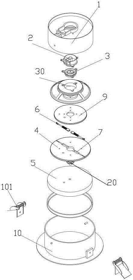
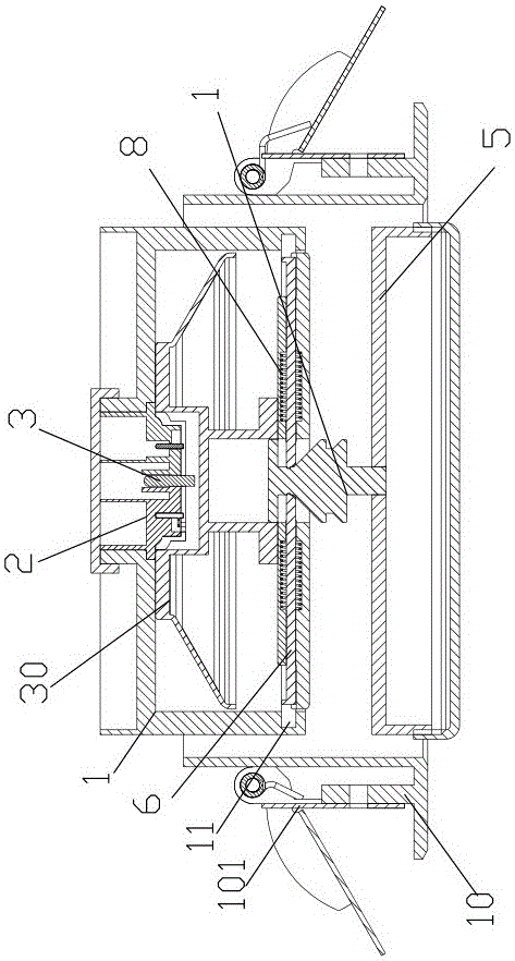
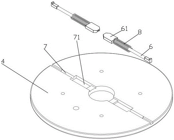
[0029] like Figure 1~Figure 6 The shown embodiment 1 of a detachable lamp includes an electrical coupling part, a lamp base on which the lighting lamp is fixed, and a fixing seat 1. The lighting lamp is connected to the electrical coupling part, and the electrical coupling part includes a The upper coupling part 2 of the seat and the lower coupling part 3 fixed on the lamp base, the upper coupling part 2 includes an annular conductive wall 21 and a central cylinder 22, the central cylinder 22 is insulated and fixed on the outer peripheral wall 21, and the central cylinder 22 A conductive sheet is provided, and the conductive sheet is connected to the power supply line, and the conductive wall 21 is connected to the power supply line. The lower coupling part 3 includes a conductive shaft 31 that slides with the central cylinder and a contact ring 32 that slides with the conductive wall 21. The surrounding wall of the upper coupling part 2 There are three installation platforms...

Embodiment 2

[0032] like figure 1The shown embodiment 2 of a detachable lamp includes an electrical coupling part, a lamp base 44 on which the lighting lamp is fixed, and a fixing seat 41. The lighting lamp is connected to the electrical coupling part, and the electrical coupling part includes a The upper coupling part 42 of the fixed seat and the lower coupling part 43 fixed on the second fixed disk 49, the upper coupling part 42 includes an annular conductive wall 421 and a central cylinder 422, the central cylinder 422 is insulated and fixed on the outer peripheral wall 421, and the center The barrel 422 is provided with a conductive sheet, the conductive sheet is connected to the power supply line, and the conductive wall 421 is connected to the power supply line. The lower coupling part 43 includes a conductive shaft 431 that slides with the central barrel and a contact ring 432 that slides with the conductive wall 421. The upper coupling part 42 Three installation platforms 423 are a...


PUM


Abstract

The invention discloses a novel lamp. The novel lamp comprises a fixing base, an electrical coupling part and a lamp base fixedly provided with an illumination lamp, wherein the fixing base, the electrical coupling part and the lamp base are sequentially arranged from top to bottom. The illumination lamp is connected with the electrical coupling part. A mounting shaft capable of sliding up and down is arranged in the center portion of the lamp base in an up-down sliding manner. A first fixing groove and a second fixing groove are formed in the peripheral wall of the mounting shaft from top to bottom. At least one positioning pin capable of telescopically sliding is arranged on the lamp base. The tail ends of the positioning pins are arranged in the first fixing groove or the second fixing groove in an abutted manner. Positioning grooves allowing the positioning pins to be embedded therein for positioning are formed in the inner wall of the fixing base. According to the novel lamp, through the arranged positioning pins, the positioning pins are embedded into the positioning grooves in the fixing base after the mounting shaft is pressed so that the lamp base can be fixed to an inner cavity of the fixing base, and the overall fixing purpose is achieved; and when the disassembly is carried out, the mounting shaft is pressed again, the positioning pins are retracted from the mounting shaft as a whole so that the initial ends of the positioning pins can be disengaged from the positioning grooves to be quickly disassembled, and the quick disassembly purpose is achieved.

Description

technical field [0001] The invention relates to the field of lamps, in particular to a novel lamp. Background technique [0002] Downlight is a kind of lamp. Downlight is a kind of lighting fixture embedded in the ceiling with light down. Its biggest feature is that it can maintain the overall unity and perfection of architectural decoration, and will not damage the ceiling art because of the setting of lamps. perfect unity. The lighting lamp and the lamp holder of the traditional downlight are integrated into one body, and are fixedly connected by a fastening device or bolts. When the lighting lamp needs to be replaced, it needs to be disassembled as a whole, and then the fastening structure or bolts are opened to replace the lighting lamp, which is troublesome to disassemble. , and because downlights are often hung at high places, it is inconvenient to take them down. Contents of the invention [0003] The object of the present invention is to provide a lamp that is co...

Claims


Application Information

Patent Timeline
Patent Type & Authority Applications(China)
IPC IPC(8): F21S8/02F21V21/00F21V17/14
CPCF21S8/026F21V17/14F21V21/00
Inventor 任闫涛朱惠玉
Owner 任闫涛
Why Eureka
Try Eureka