Lamp capable of being demounted rapidly

A lamp and fast technology, which is applied to the parts of the lighting device, the cooling/heating device of the lighting device, the lighting device, etc., can solve the problems of troublesome and inconvenient removal, etc., so as to reduce the difficulty of opening the mold and reduce the cost effect

Pending Publication Date: 2017-05-17
任闫涛
View PDF6 Cites 6 Cited by
  • Summary
  • Abstract
  • Description
  • Claims
  • Application Information

AI Technical Summary

Problems solved by technology

[0002] Most of the lighting fixtures are installed on the top to maximize the range of illumination, or directly irradiate above the display items to achieve the best lighting effect. The traditional lighting lamps and lamp holders are integrated into one body and connected by fast

Method used


Image

  • Lamp capable of being demounted rapidly
  • Lamp capable of being demounted rapidly
  • Lamp capable of being demounted rapidly

Examples


Embodiment 1

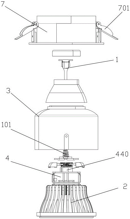
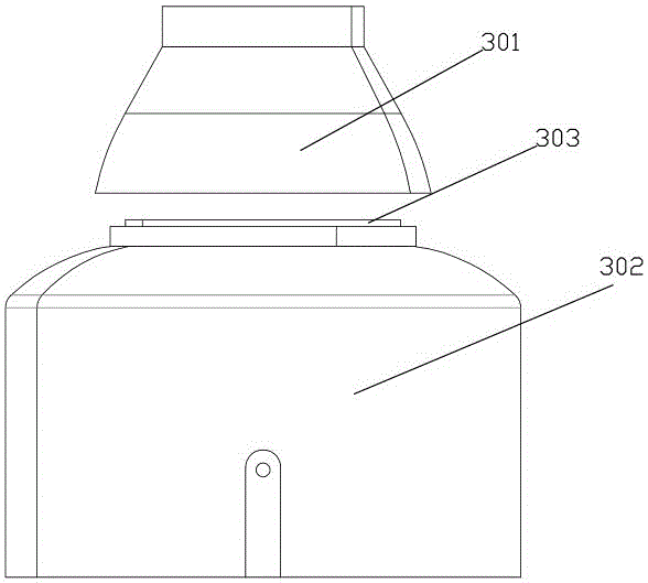
[0025] Such as figure 1 Embodiment 1 of a quick detachable lamp shown in , includes an electrical coupling part 1, a lighting lamp, a lampshade 2, an outer protective cover 3 and a fixing seat 4, the lighting lamp is connected to the electrical coupling part 1, and the electrical coupling part 1 It can be slid up and down and assembled on the upper end of the fixed seat 4, and a spring 101 is pressed between the electric coupling part 1 and the fixed seat 4. The lighting lamp is fixed in the lampshade 2, and the lighting lamp is electrically connected to the electric coupling part 1, and the fixing seat 4 is fixed on the lampshade 2 The upper end of the fixed seat 4 includes an upper fixed seat 401 and a lower fixed seat 402, and two matching positioning pins 40 are slidably assembled between the upper fixed seat 401 and the lower fixed seat 402, and a spring 410 is passed between the positioning pins 41. A thrust away from them is applied to both of them, and the positioning ...

Embodiment 2

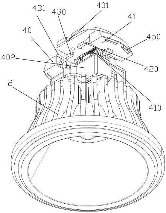
[0032] Such as Figure 4 The difference between Embodiment 2 of a quick-detachable lamp shown in and Embodiment 1 is that a cylinder 201 is provided at the lower end of the electrical coupling part 21, and a spring 202 is sleeved on the cylinder 201. The cylinder 201 Slidably inserted into the middle of the fixed seat, the fixed seat includes an upper fixed seat 310 and a lower fixed seat 320, two slidable positioning pins 50 are arranged between the upper fixed seat 310 and the lower fixed seat 320, between the two positioning pins The space is composed of pressing rod 510, sleeve rod 520, swimming rod 530, spring 540 and ejector rod 550. The structure of pressing rod 510, sleeve rod 520, swimming rod 530, spring 540 and ejector rod 550 is the same as that of the ballpoint pen. Similarly, to achieve the purpose of pressing the two matching positioning pins 50 to shrink and then pressing and popping, wherein the pressing rod 510 is fixed on the positioning pin 50 by plugging, ...

Embodiment 3

[0037] Such as Figure 5and Image 6 The embodiment 3 of a quick detachable lamp shown in , differs from the embodiment 1 in that two guide columns 501 extend from the fixed end of the positioning pin 5, and each guide column 501 is sleeved with a compression spring. 502 , the guide column 501 is provided with a stepped surface for pressing the compression spring 502 , and two corresponding guide columns 501 share a compression spring 504 . The free end of locating pin 5 extends out the peripheral wall of fixing seat, and locating pin 5 is provided with positioning device, and fixing seat comprises upper fixing seat 403 and lower fixing seat 404, and upper fixing seat 403 is provided with the coordinating limit device with positioning device , the positioning device is a positioning protrusion 503 provided on the upper end surface of the positioning pin, and the limiting device is a groove 405 provided on the upper fixing seat 403. When the positioning protrusion 503 and the ...


PUM


Abstract

The invention discloses a lamp capable of being demounted rapidly. The lamp comprises a coupling part, a lighting lamp, a lampshade, an outer protection cover and a fixing base, and a positioning pin is assembled on the fixing base in a sliding manner; and a buckling device is further included, the outer protection cover is arranged on the periphery of the lampshade in a surrounding manner and comprises an upper cover body and a lower cover body, the lower end of the upper cover body is connected with the upper end of the lower cover body, and a positioning convex ring is arranged at the upper end of the lower cover body. According to the lamp, the positioning pin is arranged, in the mounting process, and the positioning pin is in lap joint to the positioning convex ring after being pushed and pressed to the interior of the outer protection cover, so that the lighting lamp, the fixing base and the lampshade are fixed into the outer protection cover, and the aim of overall fixation is achieved; and in the demounting process, the positioning pin is pushed to the interior of the outer protection cover continuously, after the buckling device on the positioning pin are buckled, the free end of the positioning pin stenches into the fixing base, the lighting lamp, the fixing base and the lampshade are separated at the time, and the aim of rapid replacing is achieved.

Description

technical field [0001] The invention relates to the field of quickly disassembled and assembled lamps, in particular to a rapidly disassembled and assembled lamp. Background technique [0002] Most of the lighting fixtures are installed on the top to maximize the range of illumination, or directly irradiate above the display items to achieve the best lighting effect. The traditional lighting lamps and lamp holders are integrated into one body and connected by fastening devices or bolts. When the lighting lamp needs to be replaced, it needs to be disassembled as a whole, and then the fastening structure or bolts need to be opened to replace the lighting lamp. It is hung on a high place, and there are obstacles below, so it is inconvenient to remove. Contents of the invention [0003] The object of the present invention is to provide a quick dismountable lamp which is convenient for installation and disassembly, and realizes the function of being installed by one press and ...

Claims


Application Information

Patent Timeline
IPC IPC(8): F21S8/02F21V23/06F21V17/16F21V29/508F21V29/71F21V29/74F21Y115/10
CPCF21S8/026F21V17/164F21V23/06F21V29/508F21V29/71F21V29/74
Inventor 任闫涛朱惠玉
Owner 任闫涛
Why Eureka
Try Eureka