
Refrigerator power-assisted door handle assembly and refrigerator

A technology for door handles and refrigerators, which is applied to household refrigerators, lighting and heating equipment, coolers, etc., to achieve the effect of improving experience

Active Publication Date: 2017-02-01
HISENSE(SHANDONG)REFRIGERATOR CO LTD
View PDF9 Cites 13 Cited by
  • Summary
  • Abstract
  • Description
  • Claims
  • Application Information

AI Technical Summary

Problems solved by technology

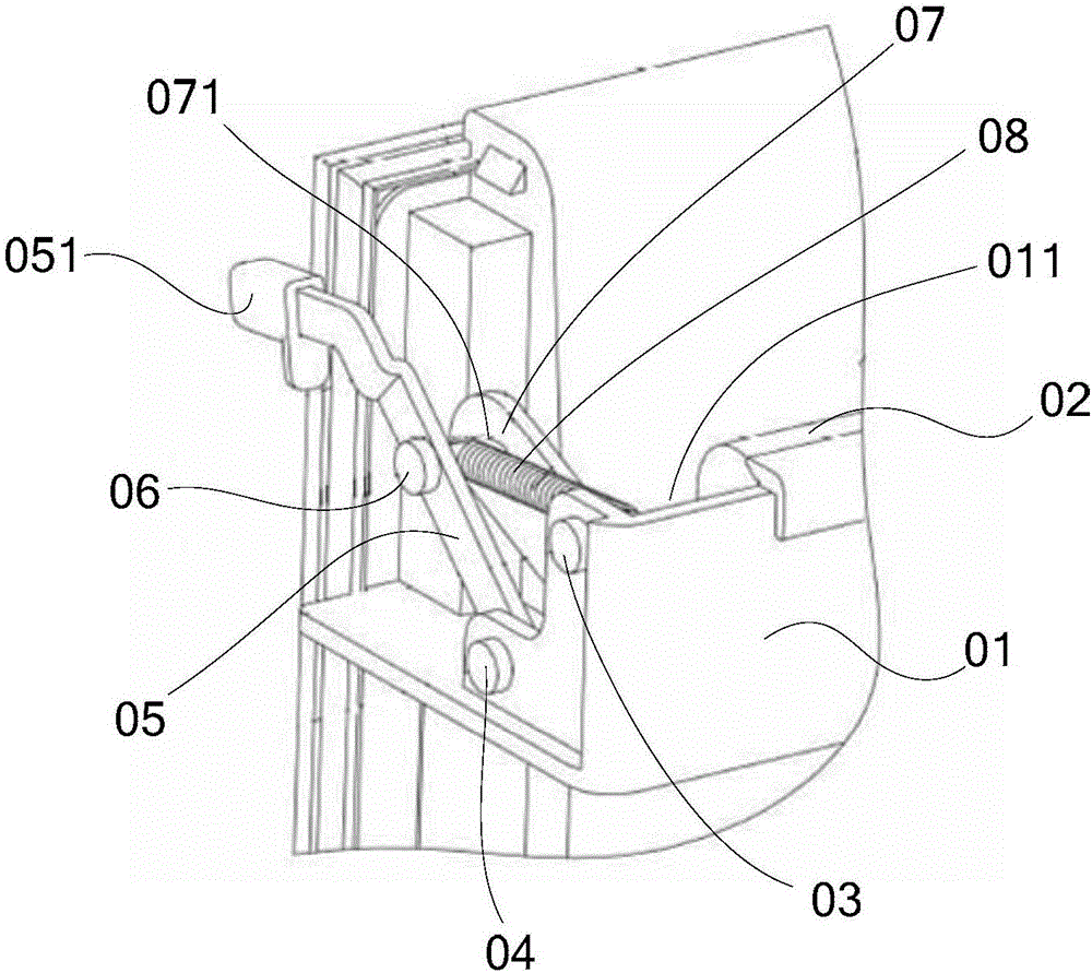
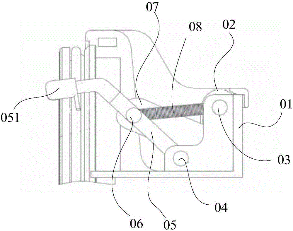
[0004] The inventor found that the existing refrigerator power-assisted door handle assembly has at least the following problems: the handle assembly can convert the rotation transmission of the handle 02 held by the human hand into an outward extension push action, but when the user uses the handle assembly to replace the refrigerator door seal and the box When the body shell is pushed out of the gap, the moment arm of the handle 02 rotation moment is the vertical distance from the bottom edge of the handle 02 to the axis of the first pin 03, and the force arm of the resistance moment is the axis of the first pin 03 to the axis of the positioning pin 06 The vertical distance, the moment arm of the resistance moment is longer than the moment arm of the handle 02 rotation moment, so the user has to exert a greater force on the handle 02 to push the refrigerator door seal and the box shell away

Method used


Image

  • Refrigerator power-assisted door handle assembly and refrigerator
  • Refrigerator power-assisted door handle assembly and refrigerator
  • Refrigerator power-assisted door handle assembly and refrigerator

Examples


Embodiment Construction

[0018] The following will clearly and completely describe the technical solutions in the embodiments of the present invention with reference to the accompanying drawings in the embodiments of the present invention. Obviously, the described embodiments are only some, not all, embodiments of the present invention. Based on the embodiments of the present invention, all other embodiments obtained by persons of ordinary skill in the art without making creative efforts belong to the protection scope of the present invention.

[0019] In describing the present invention, it is to be understood that the terms "center", "upper", "lower", "front", "rear", "left", "right", "vertical", "horizontal", The orientations or positional relationships indicated by "top", "bottom", "inner", "outer", etc. are based on the orientations or positional relationships shown in the drawings, and are only for the convenience of describing the present invention and simplifying the description, rather than in...


PUM


Abstract

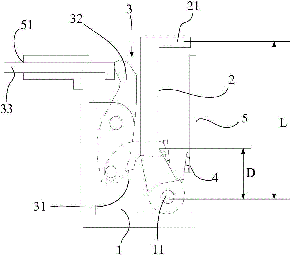
The invention discloses a refrigerator power-assisted door handle assembly and a refrigerator, and relates to the technical field of refrigerators. The refrigerator power-assisted door handle assembly is invented in order to solve the problem that when users use an existing refrigerator handle assembly to eject a refrigerator door away from a refrigerator body, a large amount of labor can be consumed. The refrigerator power-assisted door handle assembly comprises a support, a handle, a connecting rod mechanism and a reset piece. One end of the handle in the width direction is hinged to the support through a rotating shaft, and the other end of the handle is a hand-pulling end. The connecting rod mechanism comprises a first connecting rod, a second connecting rod and an ejector rod. The first end of the first connecting rod is connected with the handle, and the second end of the first connecting rod is hinged to the first end of the second connecting rod. The second end of the second connecting rod abuts against the first end of the ejector rod, and the middle part of the second connecting rod is hinged to the support. The ejector rod can slide linearly relative to the support. The second end of the ejector rod is used for abutting against the refrigerator body of the refrigerator, and the distance from the hand-pulling end of the handle to the rotating shaft is larger than the distance from the connecting point of the handle and the first connecting rod to the rotating shaft. The reset piece is used for applying reset force to the handle. The refrigerator power-assisted door handle assembly can be used in refrigerator power-assisted doors.

Description

technical field [0001] The invention relates to the technical field of refrigerators, in particular to a refrigerator power-assisted door handle assembly and a refrigerator. Background technique [0002] At present, the refrigerator door is equipped with a magnetic sealing strip, which can ensure that the refrigerator remains sealed when the door is closed. It is a large-volume refrigerator or freezer product. The door is generally relatively large and heavy. The magnetic sealing strip is relatively long and has a strong magnetic force. If there is no power-assisted handle to open the gap between the refrigerator door and the cabinet, it will cause the user to open the refrigerator It is more difficult to open the door. [0003] An existing refrigerator door handle assembly such as figure 1 As shown, the decorative strip 01 is included, and the decorative strip 01 has a strip-shaped groove 011, and a strip-shaped handle 02 is hinged in the groove 011. The two ends of the h...

Claims


Application Information

Patent Timeline
Patent Type & Authority Applications(China)
IPC IPC(8): F25D23/02F25D11/00
CPCF25D11/00F25D23/02F25D23/028
Inventor 丁恩伟王美艳寇淑文宿孝庆王海燕胡哲
Owner HISENSE(SHANDONG)REFRIGERATOR CO LTD
Learn More