
Stepped hole method-based internal residual stress measurement method

A technology of internal residual stress and measurement method, which is applied in the direction of force/torque/work measuring instrument, measuring device, instrument, etc., can solve the problems of workpiece damage, difficulty in pasting strain gauges, and enlargement of large hole diameter, etc., so as to prevent damage , high calculation accuracy, convenient and efficient operation

Active Publication Date: 2017-02-01
XI AN JIAOTONG UNIV
View PDF8 Cites 14 Cited by
  • Summary
  • Abstract
  • Description
  • Claims
  • Application Information

AI Technical Summary

Problems solved by technology

There are many deficiencies in the stepped hole method. For example, this method must ensure that the large hole has a large diameter and the bottom is very flat so that the strain gauge can be pasted; when the drilling depth reaches (1~1.2)d (large hole diameter), the strain gauge The pasting operation is difficult. If you want to continue to measure the residual stress in the deeper part of the workpiece, you must enlarge the aperture of the large hole, which will inevitably cause greater damage to the workpiece.

Method used


Image

  • Stepped hole method-based internal residual stress measurement method
  • Stepped hole method-based internal residual stress measurement method
  • Stepped hole method-based internal residual stress measurement method

Examples


Embodiment Construction

[0040] The present invention is described in further detail below in conjunction with accompanying drawing:

[0041] The internal residual stress measuring method based on the stepped hole method of the present invention comprises the following steps:

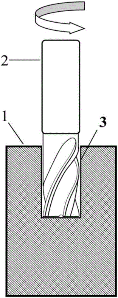
[0042] 1) Using the milling cutter 2 to mill out the concave hole 3 on the end surface of the workpiece 1 to be measured according to the preset measurement depth;

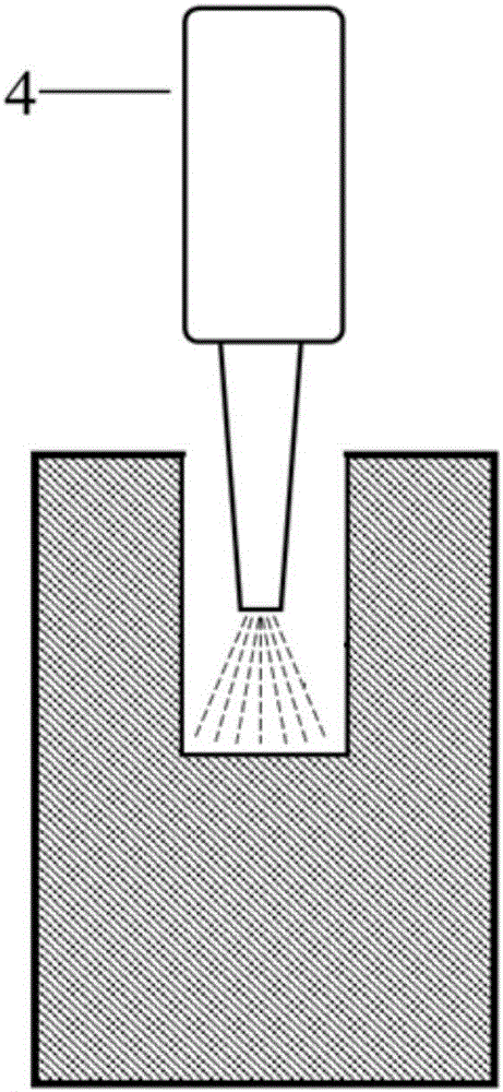
[0043] 2) cleaning the bottom surface of the concave hole 3 for the residue generated during the process of making the concave hole 3, then extending the spray pipe 4 into the concave hole 3, and evenly spraying matt white paint on the bottom of the concave hole 3;

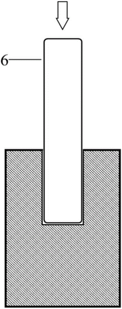
[0044] 3) Make the stamp 6, wherein, the end face of the stamp 6 is engraved with some marking points 7, then the stamp 6 is inserted into the concave hole 3, and the marking points 7 are printed on the bottom surface of the concave hole 3;

[0045] 4) Obtain the initial state information of the marki...


PUM

PropertyMeasurementUnit
Diameteraaaaaaaaaa
Diameteraaaaaaaaaa

Abstract

The present invention discloses a stepped hole method-based internal residual stress measurement method. The method includes the following steps that: 1) an end surface of a workpiece to be measured is milled through using a milling cutter according to a preset measurement depth, so that a recessed hole can be formed at the end surface of the workpiece to be measured; 2) residuals on the bottom surface of the recessed hole which are generated in the production process of the recessed hole are cleaned, and a spray tube is inserted into the recessed hole, and the bottom of the recessed hole is uniformly sprayed and coated with matte white paint; 3) a seal is produced, a plurality of marking points are engraved on an end surface of the seal, and the seal is inserted into the recessed hole, and the bottom surface of the recessed hole can be printed with marking points; 4) the initial state information of the marking points of the bottom surface of the recessed hole is obtained; 5) the center of the bottom surface of the recessed hole is drilled through using a blind hole method, so that a blind hole can be formed at the center of the bottom surface of the recessed hole; 6) residuals generated in the drilling of the blind hole are cleaned, and then, the final state information of the marking points of the bottom surface of the current recessed hole is obtained; and 7) the residual stress state of the center of the bottom surface of the recessed hole is calculated. With the method adopted, the measurement of the internal residual stress of a large-depth portion of a workpiece can be realized, measurement accuracy is high, and the workpiece will not be damaged.

Description

technical field [0001] The invention belongs to the technical field of residual stress testing, and relates to a method for measuring internal residual stress based on a stepped hole method. Background technique [0002] Residual stress refers to the stress that remains inside the workpiece to maintain balance after removing various external factors that generate stress during the manufacturing process of the workpiece. The existence of residual stress will significantly affect the various mechanical properties of the workpiece, and affect the dimensional accuracy and stress corrosion resistance of the workpiece. Therefore, the measurement of residual stress is particularly important to ensure the reliability and safety of the workpiece during service important. [0003] According to whether it will cause damage to the workpiece, the residual stress measurement method can be divided into two categories, one is non-destructive measurement method, also known as physical metho...

Claims


Application Information

Patent Timeline
IPC IPC(8): G01L5/00
CPCG01L5/0047
Inventor 张林杰白清林殷咸青宁杰杨健楠裴俊宇刘江哲张建勋
Owner XI AN JIAOTONG UNIV
Learn More