
Circulating Current Suppression Method in Power System

A circulation suppression and power system technology, applied in the direction of single-network parallel feeding arrangement, etc., can solve the problems of poor voltage stabilization characteristics and soft power supply characteristics, and achieve the effects of suppression of circulation, fast response speed, and simple control

Active Publication Date: 2019-01-18
NANJING UNIV OF SCI & TECH
View PDF6 Cites 0 Cited by
  • Summary
  • Abstract
  • Description
  • Claims
  • Application Information

AI Technical Summary

Problems solved by technology

However, while the current-limiting inductor suppresses the circulating current, the characteristics of the power supply are softened due to its voltage drop, and the voltage stabilization characteristics are deteriorated.

Method used


Image

  • Circulating Current Suppression Method in Power System
  • Circulating Current Suppression Method in Power System
  • Circulating Current Suppression Method in Power System

Examples


Embodiment

[0077] According to Table 1, design the circulation impedance parameters

[0078] Table 1 Circulating Impedance Design Parameters

[0079] parameter

parameter

L

6mH

G i

1.85

R

0.001ohm

k pwm

10

k P

2

k I

10000

k i

2.8

k

2 / 5 / 10 / 20

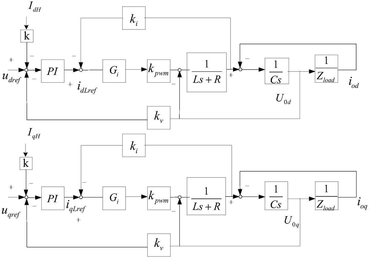
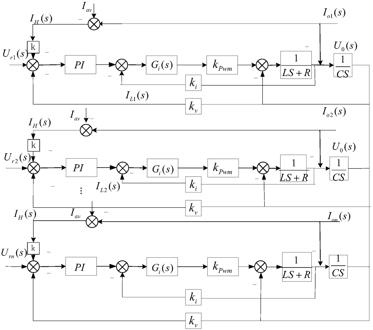
[0080] available Figure 4 Shown are the Bode diagrams of circulating impedance at different values ​​of k, and the Bode diagrams of circulating impedance correspond to k=20, k=10, k=5, and k=2 respectively from top to bottom; Figure 4 It can be seen that the circulating current impedance between the parallel running inverter power supplies with instantaneous circulating current feedback is resistive and inductive in the middle frequency band, and the proportion of resistive resistance is relatively large. As the feedback coefficient increases, the impedance amplitude increases and changes significantly.

[0081] It is set that there is a difference in th...


PUM


Abstract

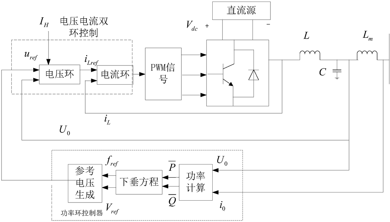
The invention relates to a circulating current suppression method of a power system. The method comprises the steps of respectively calculating three-phase circulating current of various parallel inverters by sampling output current of the parallel inverters; obtaining d-axis components and q-axis components of the circulating current through transformation of the circulating current of the parallel inverters from a three-phase static coordinate to a two-phase synchronous rotating coordinate; and adding the d-axis components and the q-axis components of the circulating current to voltage and current loop control of droop control as disturbance, obtaining reference voltage and generating six paths of PWM drive signals to drive on / off of bridge arm switch tubes of the inverters to control inverter output. The equivalent output impedance is not affected, so that power distribution is not affected and the effects of accurately distributing reactive power and suppressing the circulating current can be achieved.

Description

technical field [0001] The invention belongs to the field of microgrid control, in particular to a power system circulation suppression method. Background technique [0002] When inverters are connected in parallel, it is necessary to ensure that the output voltage, frequency, phase and amplitude of all inverters are consistent, otherwise a circulating current will be generated between the inverters. The circulating current will not only increase the burden on the switching elements and increase the system loss, but also damage the power devices and cause the system to collapse in severe cases, resulting in power supply interruption. [0003] In the traditional droop control, the power sharing control strategy is used for current sharing control. The power detection can only detect the power generated by the fundamental voltage and current, so that the low-order harmonics generated by the low-order harmonic voltage difference between the inverters Circulation cannot be effe...

Claims


Application Information

Patent Timeline
Patent Type & Authority Patents(China)
IPC IPC(8): H02J3/38H02J3/50
CPCH02J3/38H02J3/50
Inventor 吕广强耿严岩何绒顾伟
Owner NANJING UNIV OF SCI & TECH
Learn More