Spline shaft structure applicable to end face polishing operation of work piece, and polishing equipment

A technology for spline shafts and workpieces, applied in grinding/polishing equipment, metal processing equipment, grinding workpiece supports, etc., can solve problems such as low efficiency and poor parallelism, improve uniformity and parallelism, and avoid parallelism The degree is not good, the effect of improving production efficiency

Active Publication Date: 2017-02-08
漳州盈塑工业有限公司
5 Cites 0 Cited by

AI-Extracted Technical Summary

Problems solved by technology

[0004] In order to solve the above problems, the present invention provides a spline shaft structure and polishing equipment suitable for polishing the workpiece end surf...

Abstract

The invention discloses a spline shaft structure applicable to end face polishing operation of a work piece, and polishing equipment. The spline shaft comprises a ventilating shaft; a to-be-polished work piece fixedly sleeves the outer end part of the ventilating shaft; a steel ball idler wheel for driving the ventilating shaft and the to-be-polished work piece to do forward and backward telescopic motion is arranged at the inner end part of the ventilating shaft; the middle part of the ventilating shaft is also provided with a friction wheel for driving the ventilating shaft to rotate; moreover, the ventilating shaft is also provided with a rotary joint for inhaling compressed air; an air chamber communicating with the rotary joint is arranged inside the ventilating shaft; the air chamber extends to a position, for mounting the to-be-polished work piece, of the ventilating shaft, and a ventilating hole for making the air chamber communicate with the inner chamber of the to-be-polished work piece is arranged at the position. The spline shaft structure disclosed by the invention is capable of preventing the problem of poor parallelism caused by manual operation and the problem of low efficiency, and has the advantages of improving the production efficiency and also improving the grinding quality.

Application Domain

Belt grinding machinesGrinding feeders +2

Technology Topic

EngineeringCompressed air +4

Image

  • Spline shaft structure applicable to end face polishing operation of work piece, and polishing equipment
  • Spline shaft structure applicable to end face polishing operation of work piece, and polishing equipment
  • Spline shaft structure applicable to end face polishing operation of work piece, and polishing equipment

Examples

  • Experimental program(1)

Example Embodiment

[0031] In order to make the technical problems, technical solutions and beneficial effects to be solved by the present invention clearer and clearer, the present invention will be further described in detail below in conjunction with the accompanying drawings and embodiments. It should be understood that the specific embodiments described here are only used to explain the present invention, not to limit the present invention.
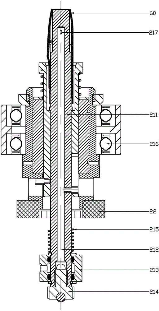
[0032] like figure 1 As shown in the present invention, a spline shaft structure suitable for workpiece polishing operations, the spline shaft 21 includes a vent shaft 211, and the workpiece 60 to be polished is socketed and fixed on the outer end of the vent shaft 211. The inner end of the ventilation shaft 211 is provided with a steel ball roller 214 that drives the ventilation shaft 211 and the workpiece 60 to be polished to move forward and backward, and the middle part of the ventilation shaft 211 is also provided with a friction wheel 22 that drives the rotation of the ventilation shaft 211 , and, the ventilation shaft 211 is also provided with a rotary joint 213 for feeding compressed air, the ventilation shaft 211 is provided with an air chamber 212 communicating with the rotary joint 213, and the air chamber 212 extends to the The vent shaft 211 is installed at the position of the workpiece 60 to be polished, and a vent hole 217 connecting the air cavity 212 with the inner cavity of the workpiece 60 to be polished is provided at this position.
[0033] In this embodiment, the outer end of the ventilation shaft 211 is provided with a stepped shaft with a reduced outer diameter. The air hole 217 communicates with the air cavity 212 of the ventilation shaft 211 . The outer peripheral wall of the ventilation shaft 211 is also configured to push the ventilation shaft 211 outward to provide elastic pressure for the polishing operation of the workpiece 60 to be polished.
[0034] During the polishing process, the aeration shaft 211 and its workpiece 60 to be polished are driven to rotate by driving the friction wheel 22. At the same time, the steel ball roller 214 is driven by a straight line to indirectly act on the aeration shaft 211, so that the aeration shaft 211 drives the workpiece 60 to be polished to expand and contract together , the compression spring can generate a certain pressure required for the polishing operation. After the polishing and grinding are completed, the compressed air is connected through the rotary joint 213, and the compressed air enters the inner cavity of the workpiece 60 through the air chamber 212 and the air hole 217 of the ventilation shaft 211, thereby The workpiece 60 is blown off to realize automatic unloading.
[0035] like figure 2 and image 3As shown, the present invention also provides a kind of polishing equipment adopting the above-mentioned spline shaft structure, which includes a frame 10, a turntable 20, an abrasive belt wheel 30, a feeding pipeline 40, and a material box 50, and the turntable 20 is vertically connected On the frame 10, the turntable 20 is provided with spline shafts 21 at circumferential intervals, and the workpiece 60 to be polished is sleeved on the outer end of the vent shaft 211 of the spline shaft 21; Comprising driving abrasive belt wheels and driven abrasive belt wheels respectively arranged on both sides of the turntable 20; the workpiece 60 to be polished rotates with the rotation of the spline shaft 21 under the drive of the friction wheel 22, and The rotation of the turntable 20 generates relative motion with the abrasive belt 31 between the driving abrasive belt wheel and the driven abrasive belt wheel, so that the abrasive belt 31 is ground and polished to the workpiece 60 to be polished; the polished workpiece 60 passes through the The feeding pipe 40 is guided and dropped into the magazine 50 .
[0036] In this embodiment, a grinding platform 33 is provided between the driving belt wheel and the driven belt wheel, and the abrasive belt 31 of the driving belt wheel is transmitted to the grinding platform 33 through a transmission gear set 32, and then Another drive gear set 32 ​​drives to the driven grinding wheel. The driving grinding wheel and the driven grinding wheel are respectively arranged on the upper side and the lower side of the turntable 20 . Also be provided with air blowing device, the rotary joint 213 of each spline shaft 21 is connected with described air blowing device respectively, and described blanking pipeline 40 is provided with more than one blanking port 41, and the workpiece after polishing is finished The spline shaft 21 is blown out of the spline shaft 21 under the pressure of the compressed air of the blowing device and enters the discharge pipe 40 from the discharge opening 41 .
[0037] In this embodiment, the ventilation shaft 211 is rotatably mounted on the turntable 20 through a rotating bearing 216, and the ventilation shaft 211 is also provided with an anti-rotation sleeve, a steel ball bushing, and a bush seat in sequence, and the rotating bearing 216 is set On the bushing seat, the friction wheel 22 is fixedly connected with the anti-rotation sleeve through the key pin, and the friction wheel 22 is driven to drive the bushing seat, steel ball bushing, steel ball roller, ventilation shaft, anti-rotation sleeve and other parts to be polished together. The workpiece rotates as a whole.
[0038] In the working process, first, the workpiece 60 (injection molded part) to be polished is manually loaded onto the spline shaft 21 on the turntable 20, and the motor drives the turntable 20 to rotate to transfer the workpiece to the abrasive belt 31 running opposite the product running direction During the grinding process, the spline shaft 21 provides a certain pressure, and at the same time, the spline shaft 21 drives the workpiece to rotate under the drive of the friction wheel 22, so that the uniformity and parallelism of the grinding can be guaranteed during grinding. After the grinding operation is completed, the workpiece is blown out of the spline shaft 21 under the action of compressed air and enters the unloading pipeline 40 from the unloading port 41, and is guided by the unloading pipeline 40 and falls into the material box 50 to realize automatic unloading.
[0039] The foregoing description shows and describes preferred embodiments of the present invention, and as previously stated, it is to be understood that the present invention is not limited to the form disclosed herein and should not be construed as excluding other embodiments but may be applied to various other embodiments. Combinations, modifications and circumstances, and can be modified within the scope of the inventive concept described herein, by the above teachings or by skill or knowledge in the relevant field. However, changes and changes made by those skilled in the art do not depart from the spirit and scope of the present invention, and should all be within the protection scope of the appended claims of the present invention.

PUM

no PUM

Description & Claims & Application Information

We can also present the details of the Description, Claims and Application information to help users get a comprehensive understanding of the technical details of the patent, such as background art, summary of invention, brief description of drawings, description of embodiments, and other original content. On the other hand, users can also determine the specific scope of protection of the technology through the list of claims; as well as understand the changes in the life cycle of the technology with the presentation of the patent timeline. Login to view more.

Similar technology patents

Precise extrusion molding method of thin wall long-pipe shaped parts bland and special mould

InactiveCN101332476AIncreased dimensional accuracy and material utilizationIncrease productivity
Owner:HENAN UNIV OF SCI & TECH

UV-curable colored paint composition

Owner:JIANGSU KUANGSHUN PHOTOSENSITIVITY NEW MATERIAL
Why Eureka
Try Eureka