
A wearable mechanical auxiliary arm for carrying based on the principle of leverage

A mechanically assisted, lever-principled technology, applied in manipulators, program-controlled manipulators, manufacturing tools, etc., can solve the problems of high production cost, inability to popularize and use, complex structure, etc. Effect

Active Publication Date: 2019-02-26
JINAN CITY CHANGQING DISTRICT POWER SUPPLY CO OF STATE GRID SHANDONG ELECTRIC POWER CO +1
View PDF10 Cites 0 Cited by
  • Summary
  • Abstract
  • Description
  • Claims
  • Application Information

AI Technical Summary

Problems solved by technology

[0003] The purpose of the present invention is to provide a wearable mechanical auxiliary arm for carrying based on the principle of leverage. The existing power-assisted mechanical arms are often complex in structure, and the size is customized for the user, resulting in high production costs and cannot be popularized.

Method used


Image

  • A wearable mechanical auxiliary arm for carrying based on the principle of leverage
  • A wearable mechanical auxiliary arm for carrying based on the principle of leverage
  • A wearable mechanical auxiliary arm for carrying based on the principle of leverage

Examples


Embodiment Construction

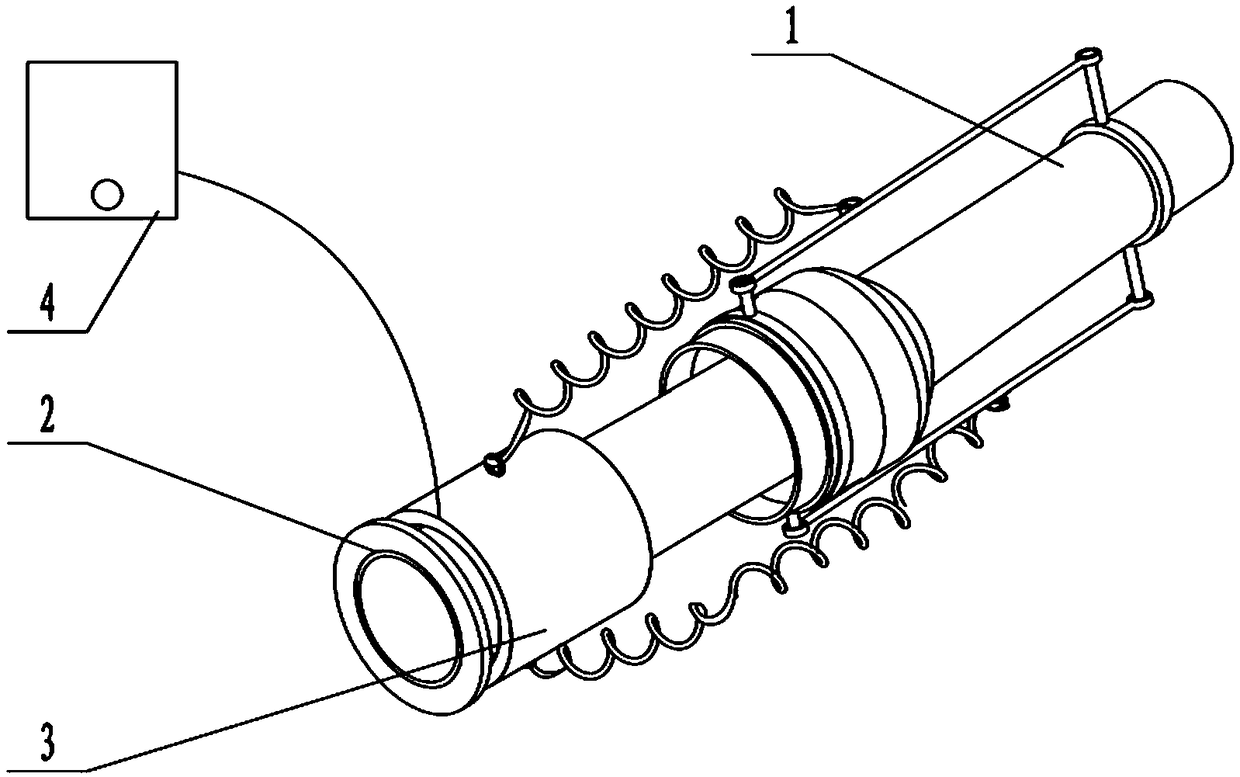
[0020] Such as Figure 1 to Figure 5 A wearable mechanical auxiliary arm for lifting based on the principle of leverage is shown, including a forearm, a rear arm 2, a power assist device 3 and a control device 4. The present invention will be described below with reference to the accompanying drawings.

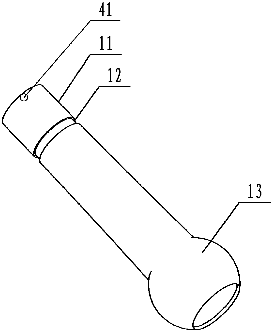
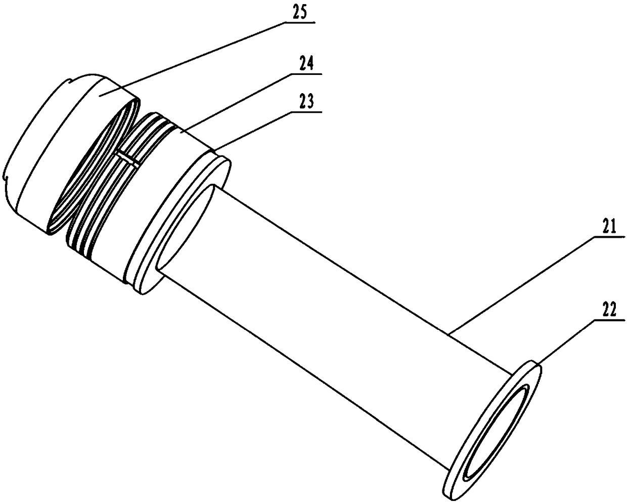
[0021] Such as figure 2 As shown, the forearm 1 is a hollow cylinder with openings at both ends, one end is a protruding end 11, and the other end is a spherical connection end 13. The outer middle of the cylinder is provided with a forearm guide groove 12, and the forearm guide groove 12 is annular, such as image 3 As shown, the rear arm 2 is a hollow cylinder with openings at both ends, including a rear arm cylinder 21 and a rear arm guide groove 23, one end is an extending end 22, the other end is a cylindrical connecting end 24, and the inner ring of the cylindrical connecting end 24 The diameter is equal to the diameter of the spherical connecting end 13, and the rear ...


PUM


Abstract

The invention discloses a lever-principle-based wearable mechanical auxiliary arm for carrying. The arm comprises a front arm, a rear arm and a power assisting device. The front arm and the rear arm are each of a hollow column with openings in two ends. One end of the front arm is a stretching-out end, the other end of the front arm is a spherical connection end, and the middle of the outer side of the column body is provided with an annular guide groove. One end of the rear arm is a stretching-in end, and the other end of the rear arm is a cylindrical connection end. The power assisting device comprises a front arm rotating frame, a connection rod, a spring, a rear arm rotating frame, a fixed magnet and a movable magnet. The two sides of the connection rod are connected with the front arm rotating frame and the rear arm rotating frame correspondingly. The fixed magnet is arranged on one side of the rear arm, and the movable magnet is an annular magnet and movably arranged on the column body of the rear arm. The two ends of the spring are connected with the connection rod and the movable magnet correspondingly. The front arm and the rear arm are connected through a universal bearing, free rotation of the front arm and the rear arm is achieved, the movement range of the arm is ensured, the connection rod is pulled through force between the magnets, the weight of carried objects is reduced, heavy objects such as a motor are omitted, the structure is simple, and the device is easy and convenient to use.

Description

technical field [0001] The invention relates to the field of power-assisted machinery, in particular to a wearable mechanical auxiliary arm for carrying based on the principle of leverage. Background technique [0002] The mechanical arm is very helpful to the direction of handling and storage. It can actively pull us to lift and reduce the weight of objects during work, thereby reducing human labor intensity and fatigue, thereby improving labor productivity and reducing the weight of objects. Work errors due to human or automated robot factors. The existing power-assisted mechanical arms are often complex in structure, and the size is tailored for the user, resulting in high production costs and cannot be popularized and used. Contents of the invention [0003] The purpose of the present invention is to provide a wearable mechanical auxiliary arm for carrying based on the principle of leverage. The existing auxiliary mechanical arm is often complex in structure and the s...

Claims


Application Information

Patent Timeline
Patent Type & Authority Patents(China)
IPC IPC(8): B25J9/00
CPCB25J9/0006
Inventor 李文博李红玲雒天宁王昭军王娜张令燕张娟
Owner JINAN CITY CHANGQING DISTRICT POWER SUPPLY CO OF STATE GRID SHANDONG ELECTRIC POWER CO
Learn More