
Automatic clamping cup tray with sensing devices

A technology of sensing device and cup holder, which is applied in transportation and packaging, special positions of vehicles, vehicle parts, etc., can solve problems such as falling under the brake, clutch or accelerator, no fixing device for the cup holder, and the water cup jumping out of the cup hole, etc. To achieve the effect of wide range of use, simple and beautiful structure

Inactive Publication Date: 2017-02-08
宁波东昊汽车部件有限公司
View PDF4 Cites 5 Cited by
  • Summary
  • Abstract
  • Description
  • Claims
  • Application Information

AI Technical Summary

Problems solved by technology

[0003] Now, automobile technology has been developed to a higher level, and the comfort of the car is also at a higher level, but there are still some places to be improved in some details. For example, there are almost no fixing devices for the existing car cup holders. It will cause the water cup to jump out of the cup hole when the car encounters uneven roads during fast moving
The water cup jumps out of the cup hole, which may damage the water cup, and may fall into the brake, clutch or accelerator. It should be driven by the driver, which will lead to safety accidents.

Method used


Image

  • Automatic clamping cup tray with sensing devices

Examples


Embodiment 1

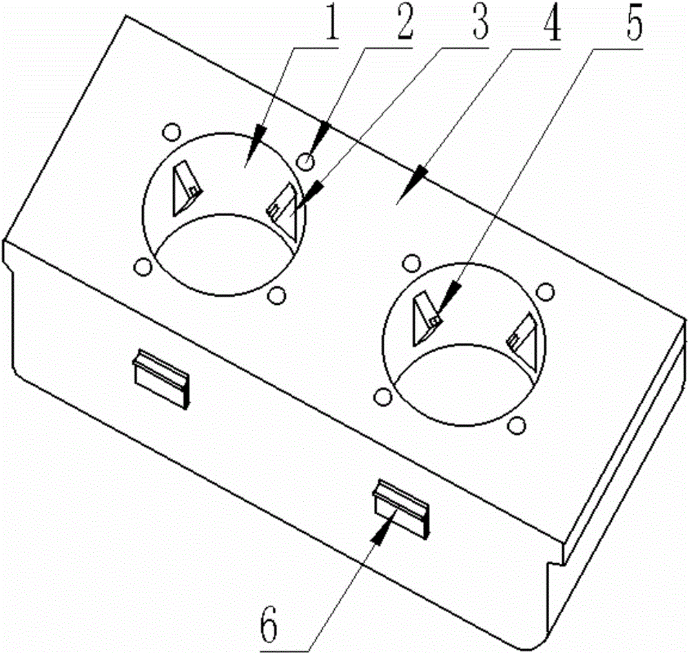
[0021] An automatic clamping cup holder with a sensing device, mainly composed of a cup hole 1, a sensing device 2, a movable cup card 3, a cup holder body 4, a pressure sensing device 5 and an installation buckle 6; the cup holder body 4. A cup hole 1 is arranged on the mirror image downwards on the upper surface, which can make the upper surface of the cup holder body 4 relatively flat, making the whole more concise and comfortable; the upper surface of the cup holder body 4 is evenly arranged along the circumference of the cup hole 1 There are 4 small holes, and the induction device 2 is installed in the small hole. The distance between the induction device 2 and the cup hole 1 is 6mm-8mm. , also under the premise of ensuring that the upper surface of the cup bracket body 4 is relatively flat, the induction device 2 is arranged, and the vertical upward setting can prevent the induction device 2 from being disturbed by the water cup; the middle part of the inner wall of the c...

Embodiment 2

[0024] This embodiment is further improved on the basis of Embodiment 1. The number of the movable cup cards 3 is 3-5 and they are jointly connected with a synchronization device. The radial height of the movable cup cards 3 along the cup hole 1 is 13mm, and the movable The contact between the cup card 3 and the water cup is set in an arc shape. 3-5 movable cup cards 3 can meet the demand for stable clamping, the movable cup card 3 is equipped with a synchronization device to make the force of each movable cup card even and keep the water cup in the center of the cup hole, the radial height and cup The variable aperture formed by the cooperation of the diameter of the hole 1 can meet the clamping requirements of most water cups on the market. The arc setting can make the contact surface between the movable cup card 1 and the water cup larger, so that the clamping is more stable.

[0025] The number of the cup holes 1 is 2, the distance between the cup holes 1 and the front and...


PUM


Abstract

The invention discloses an automatic clamping cup tray with sensing devices. The automatic clamping cup tray comprises a cup hole, the sensing devices, a plurality of moveable cup clamps, a cup tray frame, pressure sensing devices and a mounting buckle, wherein the cup hole is downward formed on an upper surface of the cup tray frame in a mirror image form; small holes are uniformly formed on the upper surface of the cup tray frame along the circumference of the cup hole; the sensing devices are arranged in the small holes; the sensing devices are arranged along upward vertical direction and are all arranged under the upper surface of the cup tray frame; the moveable cup clamps are uniformly arranged on the middle part of an inner wall of the cup hole along the circumference; the moveable cup clamps are arranged as triangular prisms and the longest edges of the moveable cup clamps are arranged on the inner wall of the cup hole; the pressure sensing devices are arranged at the contacts of the moveable cup clamps and a water cup; the moveable cup clamps can move along the radial direction of the cup hole; a control mechanism moving along the radial direction is connected with the sensing devices and the pressure sensing devices. The automatic clamping cup tray with sensing devices can automatically identify the intention of putting in and taking out the cup, so that the cup can be automatically clamped and released.

Description

technical field [0001] The invention relates to the field of auto parts, in particular to an automatic cup holder with an induction device. Background technique [0002] Automobile is a vehicle that can be driven by its own power, and can be driven by motor without the need for rails or electric power. In a broad sense, a vehicle with four wheels is generally called a car. From the end of the 19th century to the beginning of the 20th century, automobile designers devoted their energy to the development and innovation of automobile mechanical engineering. In the first half of the 20th century, after the basic structure of the car had been invented, car designers began to improve the exterior shape of the car, and successively introduced aerodynamics, fluid mechanics, ergonomics and industrial design (industrial design). Aesthetics) and other concepts, and strive to make the car meet the different needs of people of various ages, classes, and even cultural backgrounds in ter...

Claims


Application Information

Patent Timeline
Patent Type & Authority Applications(China)
IPC IPC(8): B60N3/10
CPCB60N3/101B60N3/106
Inventor 陈善龙凌扬红邓超飞胡忠伍
Owner 宁波东昊汽车部件有限公司
Learn More