Floating boat body valve

A technology of hull and gate, applied in water conservancy engineering, marine engineering, coastline protection, etc., can solve problems such as sealing, dam flood disaster, etc.

Inactive Publication Date: 2017-02-08
赵祥滨
View PDF0 Cites 1 Cited by
  • Summary
  • Abstract
  • Description
  • Claims
  • Application Information

AI Technical Summary

Problems solved by technology

[0005] However, when the dam leaks, the traditional floating hull gates cannot quickly seal with the dam breach, causing flooding downstream of the dam

Method used


Image

  • Floating boat body valve
  • Floating boat body valve
  • Floating boat body valve

Examples


Embodiment 1

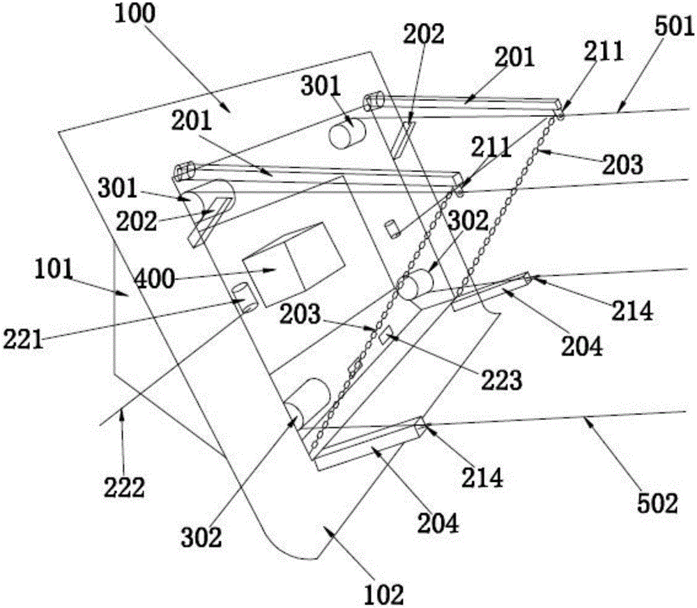
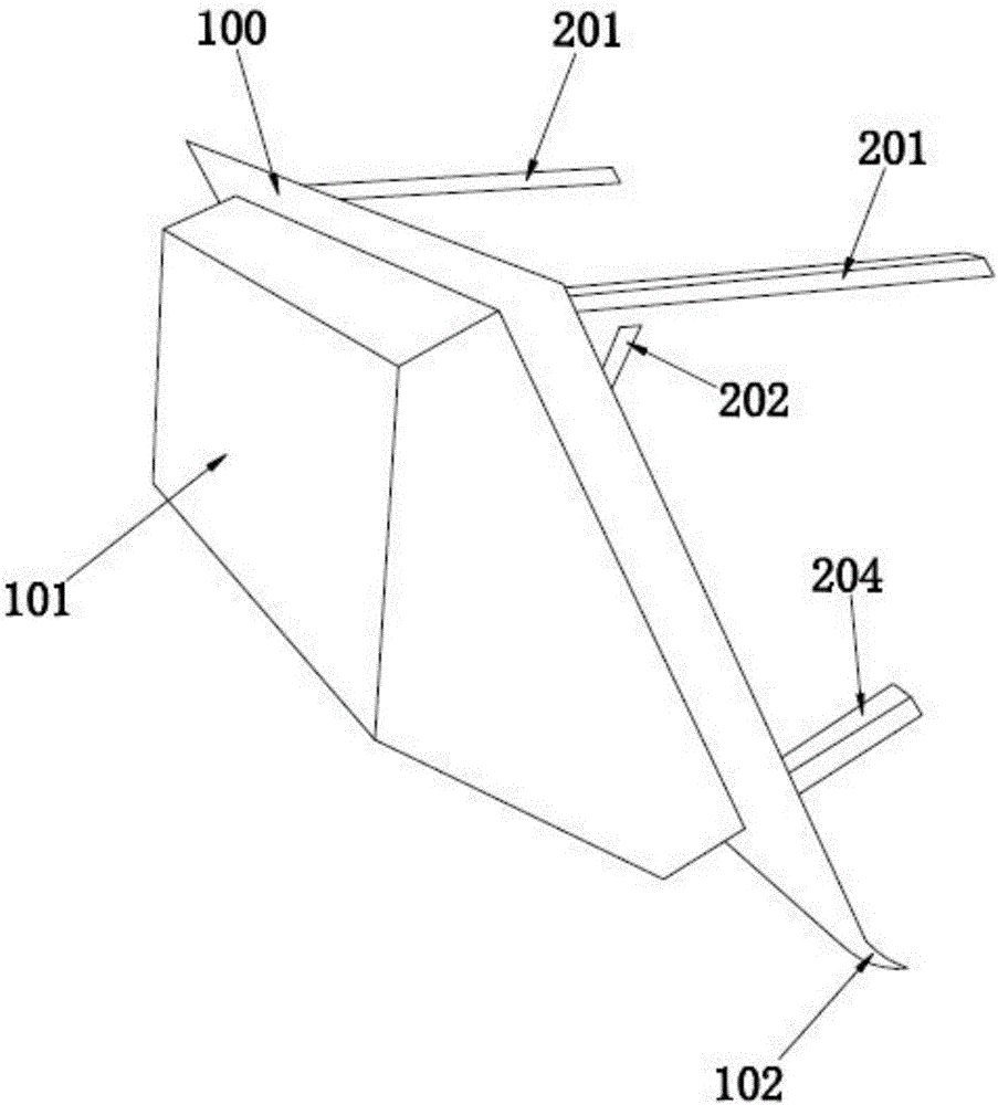
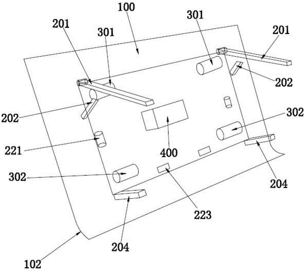
[0028] Such as Figure 1~3 shown, see figure 1 , a floating hull gate of the present invention includes

[0029] The docking plate 100 has a plate through hole in the middle;

[0030] buoyancy chamber 101, the outer end of which is sealed and fixed with the through hole of the plate;

[0031] A lever 201, one end of which is hingedly connected to the upper end of the buoyancy chamber 101, and the other end is provided with a lever collar 211;

[0032] Control column 202, its fixed end is hingedly connected with the middle part of the outer end of the buoyancy chamber 101, and its telescopic end overlaps with the middle part of the lever 201;

[0033] A stabilizing column 204, one end of which is connected to the lower end of the buoyancy chamber 101, and the other end is provided with a column rope ring 214;

[0034] Wherein, the inner upper end of the buoyancy chamber 101 is provided with an upper winch motor 301, the output shaft of the upper winch motor 301 is fixed to ...

Embodiment 2

[0050] The difference between this embodiment 2 and embodiment 1 is: see Figure 4 , the end of the lever 201 is connected to the lever collar 211 through a fine-tuning mechanism 500, and the fine-tuning mechanism 500 includes a square seat 501, a first bottom rod 511, a second bottom rod 512, a third bottom rod 513, a second bottom rod A middle seat 521, a second middle seat 522, a third middle seat 523, a first middle rod 531, a second middle rod 532, a third middle rod 533, a first push rod 541, a second push rod 542, a third push rod rod 543;

[0051] The end angle of described square seat 501 is fixed with the end of described lever 201, and the connection line of two opposite end angles of described square seat 501 is parallel with the length direction of described lever 201, and described square seat 501 is cube , the three surfaces of the square seat 501 away from the lever 201 are hingedly connected to one end of the first bottom bar 511, the second bottom bar 512, a...


PUM


Abstract

The invention discloses a floating boat body valve which comprises a butt plate (100), a floating cabin (101), a lever (201), a control post (202) and a stable post (204), wherein a plate through hole is formed in the middle of the butt plate (100). According to the floating boat body valve disclosed by the invention, an upper winch motor (301) and a lower winch motor (302) drive an upper steel wire rope (501) and a lower steel wire rope (502) to extend out and draw back, so that inclination angles of the floating cabin (101) floated on water and the butt plate (100) are adjustable, and the floating cabin (101) is controlled to be filled to a notch of a dam, and the butt plate (100) is blocked on the inner wall of the dam, and therefore, leakage stoppage work of the dam is realized.

Description

technical field [0001] The invention relates to a leak-stopping device, in particular to a floating hull gate for leak-stopping of a dam. Background technique [0002] Water Conservancy Project -------- In order to develop and utilize the river's hydraulic resources, take engineering measures on the river course, build hydraulic structures that control and control the water flow in accordance with relevant national regulations, and arrange them in a reasonable position In terms of mutual cooperation and coordination, an organic complex composed of hydraulic and water conservancy tasks is realized. Including water retaining buildings, water release buildings, etc. [0003] Dam -------- The representative form of water retaining structure is called dam. It can be divided into earth dam, gravity dam, concrete face rockfill dam, arch dam, etc. [0004] The main backwater structure in a dike hydropower station. Also known as barrage. Its function is to raise the water level of...

Claims


Application Information

Patent Timeline
Patent Type & Authority Applications(China)
IPC IPC(8): E02B7/00E02B7/50
CPCE02B7/00E02B7/50
Inventor 赵祥滨
Owner 赵祥滨
Why Eureka
Try Eureka