Anti-seismic pole

A technology of poles and shock-absorbing seats, applied in the field of transmission lines, can solve the problems of uneven settlement, easy breaking, time-consuming and laborious installation process, etc., to improve structural stability and reliability, reduce deflection or hard damage, The effect of preventing breakage or tipping

Active Publication Date: 2017-02-08
PINGDINGSHAN POWER SUPPLY ELECTRIC POWER OF HENAN
View PDF7 Cites 9 Cited by
  • Summary
  • Abstract
  • Description
  • Claims
  • Application Information

AI Technical Summary

Problems solved by technology

[0002] At present, the pole design and structural safety and stability construction of the 35KV and below power transmission and distribution lines of the power grid are relatively weak. The poles for power transmission and wiring are all set with thick cylinders at the bottom and brackets at the top, which are tree-shaped at high altitudes. , used to erect wires and cables, the bottom end of which is connected by bolts to the foundation that is simply laid underground, but this traditional way of rigidly fixing the pole to the ground is difficult to resist the vibration of the foundation or the occurrence of earthquake disasters. When an earthquake occurs, it often causes Foundation cracking and uneven settlement, etc.; when natural disasters such as strong winds, heavy snow, heavy rain, and ice cover occur, the poles will be tilted and overturned like a "domino" effect, and the entire section will even be broken and damaged. The destruction of the area and the power outage accident seriously endanger the power safety and residents' production and living electricity, and bring immeasurable losses to the national economy.
On August 14, 2013, a tornado hit Pushi Town, Luxi County, Xiangxi Autonomous Prefecture. After the tornado, the roofs of Neiwa houses in the town were overturned, and the utility poles collapsed in rows and fell on the roofs of residents or trees. More than 5 The 10 kV line was affected by the disaster, affecting nearly 100,000 residents in four villages and towns for production and living electricity. However, the current common method is to prefabricate concrete at the base, and then connect the bottom of the pole through the flange. If the concrete base is small It is easy to settle, if it is very large, it will waste a lot of resources, and the flange connection method is easy to break in the case of strong wind, vibration, etc., and there is still a big safety hazard. Therefore, how to design a new type of pole structure to make it easier to fight disasters ability greatly improved
The disadvantage of this structure is that the connection between the pole and the base is still rigid, and the earthquake resistance is not strong in the face of the shear wave and longitudinal wave of the earthquake
The disadvantage of this structure is: the structure is complicated, and the installation process is time-consuming and laborious

Method used


Image

  • Anti-seismic pole
  • Anti-seismic pole
  • Anti-seismic pole

Examples


Embodiment 1

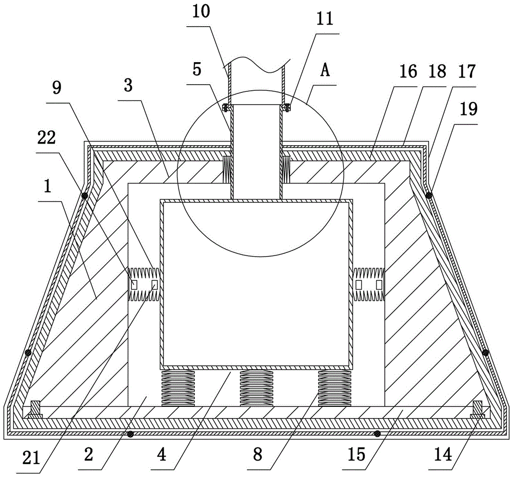
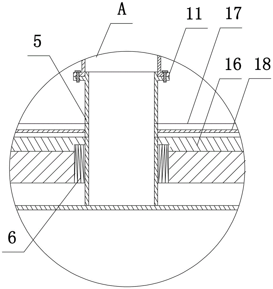
[0029] Such as Figure 1 to Figure 3 As shown, the present invention includes a pole main body 10, a moisture-proof casing and a shockproof mechanism arranged in the moisture-proof casing. The moisture-proof casing includes a symmetrically arranged front casing (not shown), a rear casing 16, and the front casing and the rear casing 16 are integrally formed. The second flange 17, the inner side of the second flange 17 of the front shell and the rear shell 16 is provided with a sealing strip 18, and the front shell and the rear shell 16 are fastened to each other and sealed and fastened by bolts 19;

[0030]The anti-shock mechanism includes a support base and a shock-absorbing structure, including a support base 1, a shock-absorbing structure, and a pole main body 10. The pole main body 10 can use a columnar hollow steel pipe, and the support base 1 is a frustum-shaped structure. , the accommodation cavity 2 is a rectangular parallelepiped columnar structure, the upper end surfa...

Embodiment 2

[0033] The present invention includes a pole main body 10, a moisture-proof casing and a shock-proof mechanism arranged in the moisture-proof casing, the moisture-proof casing includes a symmetrically arranged front casing and a rear casing 16, and the front casing and the rear casing 16 are integrally formed with a second flange 17, and the front casing A sealing strip 18 is provided on the inner side of the second flange of the rear shell 16, and the front shell and the rear shell 16 are fastened to each other by bolts 19 to seal and fasten them;

[0034] The anti-shock mechanism includes a support base and a shock-absorbing structure, including a support base 1, a shock-absorbing structure, and a pole main body 10. The pole main body 10 can use a columnar hollow steel pipe, and the support base 1 is a frustum-shaped structure. , the accommodation cavity 2 is a rectangular parallelepiped columnar structure, the upper end surface of the supporting base 1 is integrally formed w...

Embodiment 3

[0037] The structure of this embodiment is basically the same as that of Embodiment 1, the difference is: as Figure 5 As shown, four first protrusions 12 (two are shown in the figure) are arranged on the outer wall of the shock absorber 4, four second protrusions 13 are arranged on the inner wall of the accommodation cavity 2, and the air spring 9 is four and its The two ends are respectively socketed with the first protrusion 12 and the second protrusion 13 . During installation, the air spring 9 is retracted by the hydraulic or pneumatic clamping device in the prior art, and it is sleeved on the first protrusion 12 and the second protrusion 13. When an earthquake occurs, this structural design is conducive to improving the air spring. 9 structural stability.


PUM


Abstract

The invention discloses an anti-seismic pole which comprises a pole main body (10), a moisture-proof shell and an anti-seismic mechanism arranged in the moisture-proof shell, wherein the anti-seismic mechanism comprises a support base (1) and a damping structure; an air spring (9) is arranged between the damping structure and the support base; a pressure sensing module (21) and a wireless sending module (22) are arranged in the air spring (9); the wireless sending module (22) is wirelessly communicated with a wireless receiving module in a remote central control chamber; an output end of the wireless receiving module is electrically connected with a control module; the output end of the control module is electrically connected with an alarming module. According to the invention, a disc spring set and an air spring buffering component are arranged between the support base and the damping base and a damping spring is arranged between a connecting rod and a cover plate, so that the rigid damage of transverse wave and longitudinal wave of earthquake to the pole can be effectively prevented.

Description

technical field [0001] The invention belongs to the technical field of power transmission lines, and in particular relates to an anti-seismic electric pole. Background technique [0002] At present, the pole design and structural safety and stability construction of the 35KV and below power transmission and distribution lines of the power grid are relatively weak. The poles for power transmission and wiring are all set with thick cylinders at the bottom and brackets at the top, which are tree-shaped at high altitudes. , used to erect wires and cables, the bottom end of which is connected by bolts to the foundation that is simply laid underground, but this traditional way of rigidly fixing the pole to the ground is difficult to resist the vibration of the foundation or the occurrence of earthquake disasters. When an earthquake occurs, it often causes Foundation cracking and uneven settlement, etc.; when natural disasters such as strong winds, heavy snow, heavy rain, and ice c...

Claims


Application Information

Patent Timeline
IPC IPC(8): E04H12/22E02D27/42E02D31/08E02D31/06E02D33/00
CPCE02D27/42E02D31/06E02D31/08E02D33/00E02D2200/146E04H12/2253E04H12/2292
Inventor 胡军台刘春阳张逸群智勇军郭毅鹏汪锋张卫东赵元林杨玉良李居才王培川
Owner PINGDINGSHAN POWER SUPPLY ELECTRIC POWER OF HENAN
Why Eureka
Try Eureka