Thermal imaging device used for medical image

A medical imaging and thermal imaging technology, which is applied in medical science, application, and diagnosis by using light, can solve the problems of large occupied space, breakdown of switch tubes, and large volume of thermal imaging mechanism, so as to reduce the space occupied by work , Improve reliability and improve practicability

Inactive Publication Date: 2017-02-15
SHENZHEN NAISHIDI TECH DEV CO LTD
View PDF7 Cites 2 Cited by
  • Summary
  • Abstract
  • Description
  • Claims
  • Application Information

AI Technical Summary

Problems solved by technology

In the existing thermal imaging equipment, the volume of the thermal imaging mechanism is too large, so when the patient is examined, the space required is too large, resulting in a certain waste of space and reducing the practical value of the equipment; not only that , in the process of equipment work, the push-pull power supply circuit is generally used. Although the cost is low, due to the high withstand voltage requirements of the internal switch tube, it is easy to cause the breakdown of the switch tube and reduce the reliability of the working power supply. sex

Method used


Image

  • Thermal imaging device used for medical image
  • Thermal imaging device used for medical image
  • Thermal imaging device used for medical image

Examples


Embodiment Construction

[0024] The present invention is described in further detail now in conjunction with accompanying drawing. These drawings are all simplified schematic diagrams, which only illustrate the basic structure of the present invention in a schematic manner, so they only show the configurations related to the present invention.

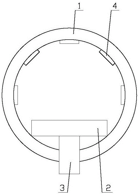
[0025] Such as Figure 1-Figure 5 As shown, a thermal imaging device for medical imaging includes a base 3, a bed board 2 horizontally arranged on the top of the base 3, and a thermal imaging mechanism;

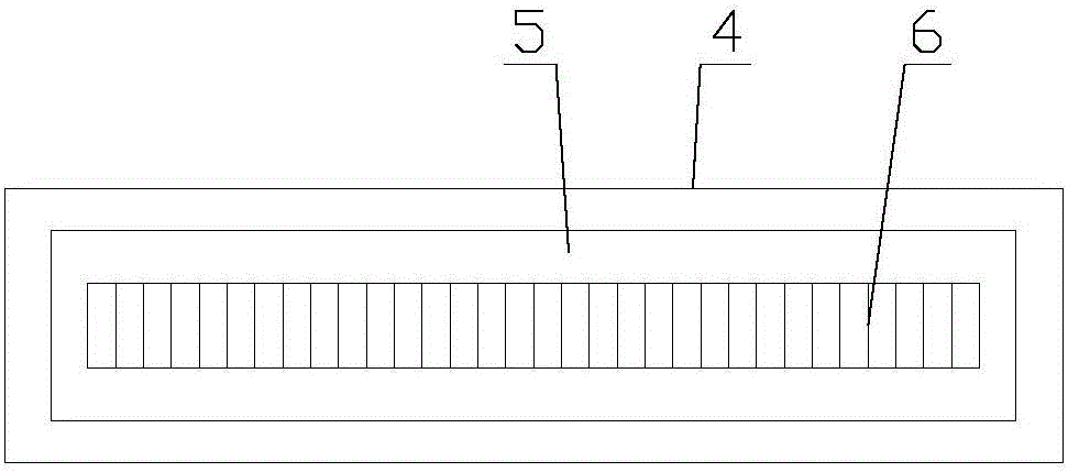
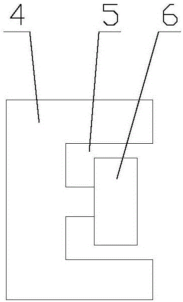
[0026] The thermal imaging mechanism includes a body 1, the vertical section of the body 1 is a ring, the base 3 and the bed board 2 are located inside the body 1, and the inner wall of the body 1 is evenly provided with a number of thermal imaging sensors 4 , the lower end of the body 1 is provided with a notch, and the two sides of the notch are provided with a moving assembly, and the body 1 is connected to the base 3 through the moving assembly;

[0027...


PUM


Abstract

The invention relates to a thermal imaging device used for a medical image. The thermal imaging device comprises a foundation base, a bed board and a thermal imaging mechanism, wherein the thermal imaging mechanism comprises a body, the vertical section of the body is a circular ring, the foundation base and the bed board are positioned inside the body, a plurality of thermal imaging sensors are uniformly arranged on the inner wall of the body, a gap is formed at the lower end of the body, moving assemblies are arranged at two sides of the gap, and the body is in transmission connection with the foundation base through the moving assemblies. For the thermal imaging device used for the medical image, a drive motor controls a drive gear to rotate through a drive shaft, the drive gear generates relative displacement with a guide bar, and then the body moves on the bed board; through the thermal imaging sensors, the check for the patient is realized, therefore, the space occupied by the device during work is greatly reduced, and the practicability of the device is improved; moreover, in the circuit of a working power supply, the coils on the primary side are reduced by one half, the withstand voltage of a switch tube is reduced by one half, and therefore, the working reliability of the working power supply is improved.

Description

technical field [0001] The invention relates to a thermal imaging device for medical imaging. Background technique [0002] Thermal imaging technology refers to the use of infrared detectors and optical imaging objectives to receive the infrared radiation energy distribution pattern of the measured target and reflect it on the photosensitive element of the infrared detector to obtain an infrared thermal image, which is consistent with the thermal image on the surface of the object corresponding to the distribution field. In layman's terms, an infrared thermal imager converts the invisible infrared energy emitted by an object into a visible thermal image. Different colors on the thermal image represent different temperatures of the measured object. [0003] Thermal imaging equipment is a device that uses thermal imaging technology to examine patients. In the existing thermal imaging equipment, the volume of the thermal imaging mechanism is too large, so when the patient is...

Claims


Application Information

Patent Timeline
Patent Type & Authority Applications(China)
IPC IPC(8): A61B5/00
CPCA61B5/0059
Inventor 李玉盛
Owner SHENZHEN NAISHIDI TECH DEV CO LTD
Why Eureka
Try Eureka