
Mold overturning and locking mechanism

A locking mechanism and mold technology, which is applied in the field of the lower mold installation mechanism of a molding machine, can solve the problems of time-consuming, complicated manual operations, and labor costs, and achieve the effect of convenient operation.

Active Publication Date: 2017-02-15
ANHUI KINGPOWER EQUIP & MOLD MFR
View PDF5 Cites 2 Cited by
  • Summary
  • Abstract
  • Description
  • Claims
  • Application Information

AI Technical Summary

Problems solved by technology

However, the manual work of fastening with screws and bolts is more complicated and time-consuming. For the situation where the mold needs to be replaced frequently, this method consumes more labor costs.

Method used


Image

  • Mold overturning and locking mechanism
  • Mold overturning and locking mechanism
  • Mold overturning and locking mechanism

Examples


Embodiment Construction

[0015] The present invention will be described in further detail below in conjunction with the accompanying drawings.

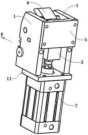
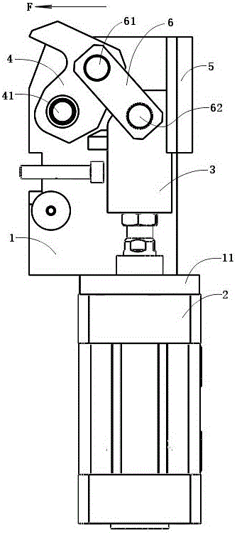
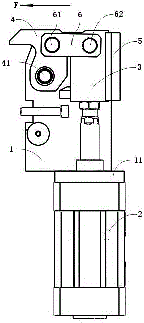
[0016] The mold turning and locking mechanism in this embodiment is a mechanism installed on the side of the lower mold table of the forming machine. Such as Figure 6 As shown, 9 is the lower die platform of the forming machine, and 91 is the mold turning locking mechanism of the present embodiment. Figure 6 Contains four mold turnover locking mechanisms 91 in. Four mold turnover locking mechanisms 91 are arranged on the edge of the lower mold platform 9 opposite in pairs, and are used to fasten the mold placed on the lower mold platform 9 . The specific structure of the mold turnover locking mechanism 91 is as follows: figure 1 , figure 2 , image 3 , Figure 4 As shown, it includes a side mounting plate 1, a cylinder 2, a traction block 3, a locking block 4, a back support plate 5 and a connecting rod 6.

[0017] There are two side mounting plates...


PUM


Abstract

The invention discloses a mold overturning and locking mechanism which comprises two side edge installing plates, an air cylinder, a traction block, a locking block, a back supporting plate and a connecting rod. The two side edge installing plates are vertically installed on a bottom plate in parallel. The back supporting plate is installed on the two side edge installing plates and located on the back portion. The locking block is composed of a transverse part and a vertical part and shaped like the Arabic numeral 7. The transverse part of the locking block is located at the top end of the vertical part of the locking block and faces the front portion of the whole mechanism. The bottom of the vertical part of the locking block is erected between the two side edge installing plates through a swing shaft. A first movable shaft is arranged at the junction of the transverse part of the locking block and the vertical part of the locking block. The traction block is located between the locking block and the back supporting plate and attached to the back supporting plate. The air cylinder is installed below the bottom plate. A piston rod of the air cylinder penetrates through the bottom plate and then is connected with the bottom of the traction block. A second movable shaft is arranged on the traction block. The two ends of the connecting rod are connected with the locking block and the traction block through the first movable shaft and the second movable shaft correspondingly.

Description

technical field [0001] The invention relates to a mold installation mechanism for a lower mold of a molding machine. Background technique [0002] In various molding equipment, the loading and unloading of the mold is always a big problem. In the prior art, the installation of the lower mold of the forming machine is generally fastened by means of screws and bolts. However, the manual work of fastening with screws and bolts is more complicated and time-consuming. For the situation where molds often need to be replaced, this method consumes more labor costs. Contents of the invention [0003] The problem to be solved by the present invention is the ease of installation of the lower mold of the forming machine. [0004] In order to solve the above problems, the scheme adopted by the present invention is as follows: [0005] A mold turning and locking mechanism, characterized in that it includes a side mounting plate, a cylinder, a traction block, a locking block, a backin...

Claims


Application Information

Patent Timeline
Patent Type & Authority Applications(China)
IPC IPC(8): B29C33/30
CPCB29C33/305
Inventor 葛孝华蒋军潘菲
Owner ANHUI KINGPOWER EQUIP & MOLD MFR
Learn More