Mobile table with brake operation transfer mechanism
A technology of braking mechanism and transmission mechanism, which is applied to vehicle parts, casters, transportation and packaging, etc., can solve the problems of complicated handling of operation lines and larger conveying form, and achieves easy disassembly and assembly operations, improved maintenance, and conveyed form. compact effect
- Summary
- Abstract
- Description
- Claims
- Application Information
AI Technical Summary
Problems solved by technology
Method used
Image

Examples
no. 1 Embodiment approach
[0055] Below, refer to Figure 1 to Figure 18 The form of the portable table for carrying out this invention is demonstrated in detail.
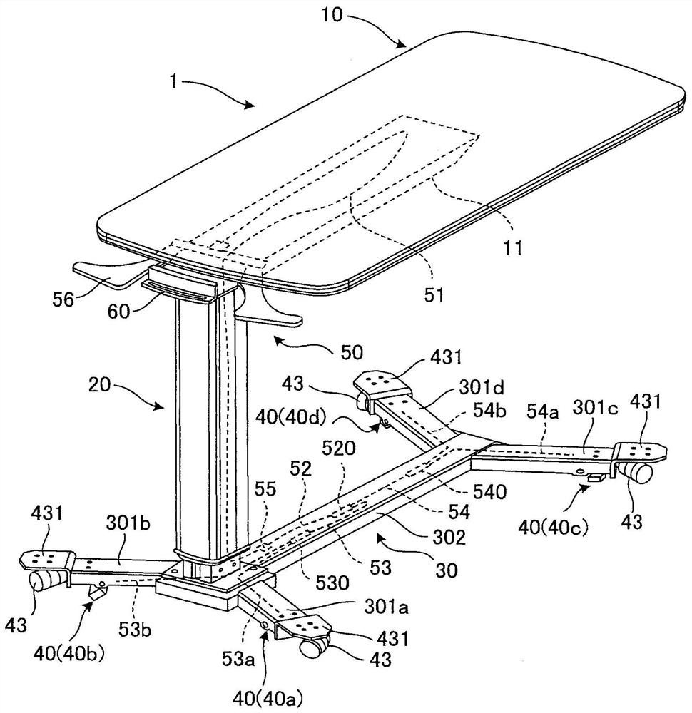
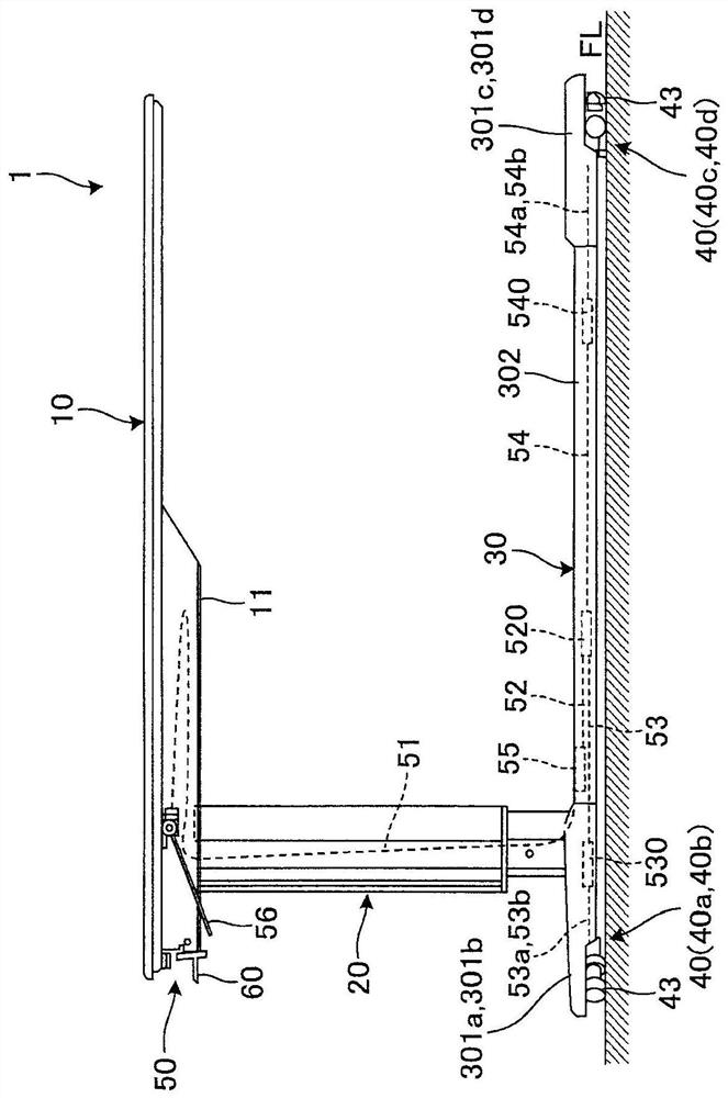
[0056] Such as figure 1 , figure 2 As shown, the mobile table 1 of the first embodiment is a bedside table, and has: a table top 10, a pillar portion 20 supporting the table top 10, a leg portion 30 supporting the pillar portion 20, and a braking mechanism for braking the table. 40. Casters 43 for moving are provided on the leg portion 30, wherein the mobile table has a brake operation transmission mechanism 50 for releasing the brake of the brake mechanism 40. As the structure of the brake operation transmission mechanism 50, it has this A characteristic configuration of the brake operation transmission mechanism of the invention.
[0057] First, the overall configuration of the portable table 1 according to the first embodiment will be described with reference to the drawings.
[0058] Such as figure 1 , figure 2 As shown, the ta...
no. 2 Embodiment approach
[0147] Next, a second embodiment of the brake operation transmission mechanism of the present invention will be described.
[0148] Figure 19 It is an explanatory diagram showing the configuration of the brake operation transmission mechanism according to the second embodiment of the present invention. In addition, in 2nd Embodiment, the same code|symbol is attached|subjected to the same structure as 1st Embodiment, and description is abbreviate|omitted.
[0149] Such as Figure 19 As shown, the brake operation transmission mechanism 150 of the second embodiment is configured to include: an operating lever 156; and a wire drive unit 170 that operates the operating lever 156 to move the first operating wire 51 .
[0150] The operating lever 156 integrally includes an operating shaft 1561 and a driving unit operating lever 1562 , and is disposed near the end of the table base 11 at the lower portion of the table top 10 .
[0151] The operation shaft 1561 is provided along th...
no. 3 Embodiment approach
[0163] Next, a third embodiment of the brake operation transmission mechanism of the present invention will be described.
[0164] Figure 20 It is an explanatory diagram showing the configuration of the brake operation transmission mechanism of the mobile table according to the third embodiment of the present invention, and the leg portion viewed from the bottom side, Figure 21 It is a detailed diagram showing the structure of the operation wire connection part constituting the brake operation transmission mechanism of the above-mentioned mobile table, Figure 22 is an explanatory diagram showing a state in which the operation wire connecting portion is installed, Figure 23 It is an explanatory diagram showing the configuration of an operation wire constituting the brake operation transmission mechanism.
[0165] In addition, in the brake operation transmission mechanism of the third embodiment, members having the same configuration as those of the brake operation transmi...
PUM
 Abstract
Description
Claims
Application Information
 - R&D
- Intellectual Property
- Life Sciences
- Materials
- Tech Scout
- Unparalleled Data Quality
- Higher Quality Content
- 60% Fewer Hallucinations
Browse by: Latest US Patents, China's latest patents, Technical Efficacy Thesaurus, Application Domain, Technology Topic, Popular Technical Reports.
© 2025 PatSnap. All rights reserved.Legal|Privacy policy|Modern Slavery Act Transparency Statement|Sitemap|About US| Contact US: help@patsnap.com