Drafting device for spinning frame

A technology of drafting device and spinning frame, applied in the direction of spinning machine, drafting equipment, yarn, etc., can solve the problem of hindering the drafting of the first roving S11

Active Publication Date: 2020-10-16
TOYOTA IND CORP
View PDF1 Cites 0 Cited by
  • Summary
  • Abstract
  • Description
  • Claims
  • Application Information

AI Technical Summary

Problems solved by technology

Thus, the drafting of the first roving S11 is hindered between the front roller 101 and the middle belt loop pair 102

Method used


Image

  • Drafting device for spinning frame
  • Drafting device for spinning frame
  • Drafting device for spinning frame

Examples


Embodiment Construction

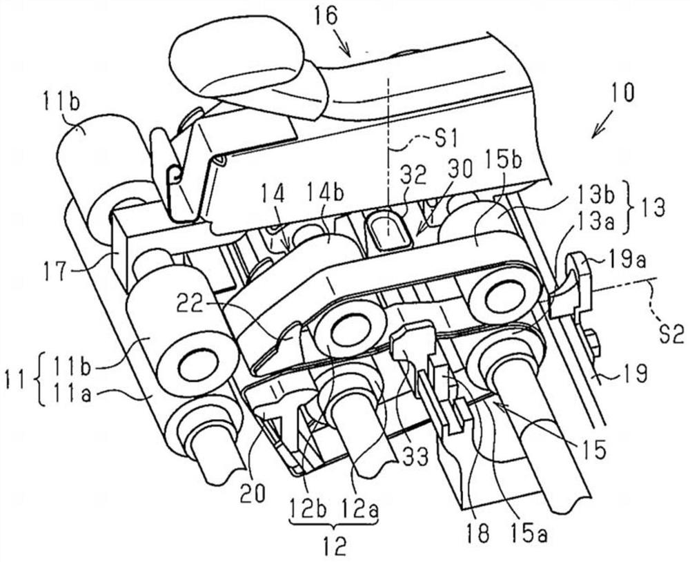
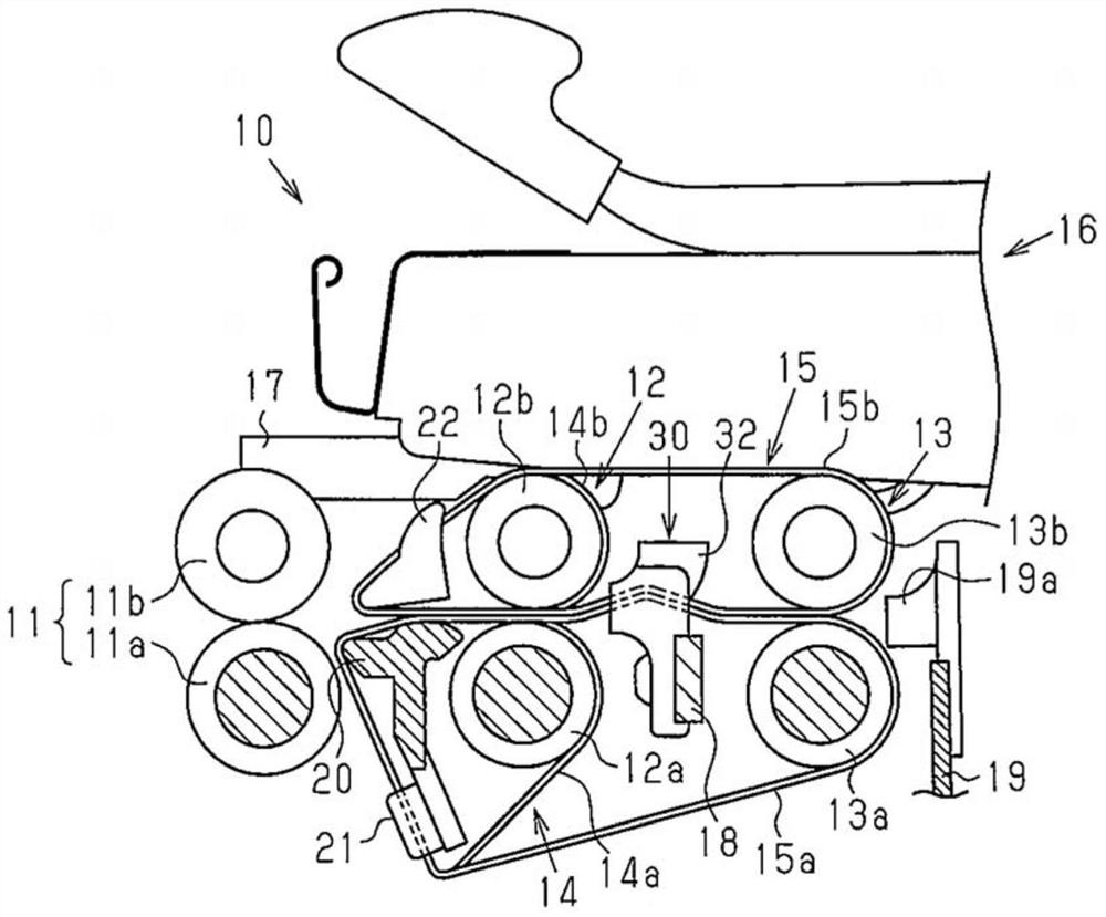
[0033] will now refer to Figure 1 to Figure 4 One embodiment of a draft device for a spinning frame will be described.

[0034] refer to figure 1 with figure 2 , the drafting device 10 includes a front roller 11 , a middle roller 12 positioned behind the front roller 11 , and a rear roller 13 positioned behind the middle roller 12 . The drafting device 10 has a three-roll configuration. The front roller 11 includes a front bottom roller 11a and a front top roller 11b. Each middle roll 12 includes a middle bottom roll 12a and a middle top roll 12b. Each rear roller 13 includes a rear bottom roller 13a and a rear top roller 13b. The drafting device 10 comprises a middle belt pair 14 feeding the first roving S1 to the front roller 11 and a rear belt pair 15 feeding the second roving S2 to the front roller 11 and a rear belt pair 15. roll 11. The drafting device 10 comprises belt loop pairs in two rows, so that both types of roving are fed to a common front roll 11 .

...


PUM


Abstract

A drafting device includes a pressing portion that increases the contact pressure between a back bottom apron and a back top apron without changing the contact pressure between a middle bottom apron and a middle top apron. This does not hinder feeding of fibers of a first roving that are held by a front bottom roller and a front top roller. Additionally, separation of fibers from a second roving and breaking of the second roving may be limited between the holding position of the front bottom roller and the front top roller and the holding position of the back bottom roller and the back top roller.

Description

technical field [0001] The present invention relates to a drafting device for a spinning frame, which spins a yarn strand while changing the combination ratio of a first roving and a second roving. Background technique [0002] This type of drafting device is disclosed, for example, in International Publication No. WO2015 / 033811. Such as Figure 16 with Figure 17 As shown, the drafting device 100 includes a front roller 101 , a middle belt loop pair 102 and a rear belt loop pair 103 . Behind the front roller 101 are located the middle pair of hoops 102 and the rear pair of hoops 103 . Each middle pair of loops 102 feeds the first roving S11 to the front roller 101 . Each rear pair of loops 103 feeds the second roving S12 to the front roller 101 . Two belt loop pairs are arranged in two rows behind the front roller 101 . [0003] The front roller 101 includes a front bottom roller 101a and a front top roller 101b. Each middle band pair 102 includes a middle bottom band...

Claims


Application Information

Patent Timeline
Patent Type & Authority Patents(China)
IPC IPC(8): D01H5/26D01H5/36
CPCD01H5/26D01H5/36D01H5/88D02G3/34
Inventor 槌田大辅佐藤江平
Owner TOYOTA IND CORP
Why Eureka
Try Eureka