Novel steel rail assembly

A technology of rails and components, applied in the direction of rails, tracks, roads, etc., can solve the problems of rail end deformation, accelerated wheel wear, etc.

Inactive Publication Date: 2017-02-15
吴明桓
View PDF10 Cites 0 Cited by
  • Summary
  • Abstract
  • Description
  • Claims
  • Application Information

AI Technical Summary

Problems solved by technology

Strong and frequent impacts gradually defo

Method used


Image

  • Novel steel rail assembly
  • Novel steel rail assembly
  • Novel steel rail assembly

Examples


Embodiment Construction

[0014] The rail assembly of the present invention can be obtained in the following manner.

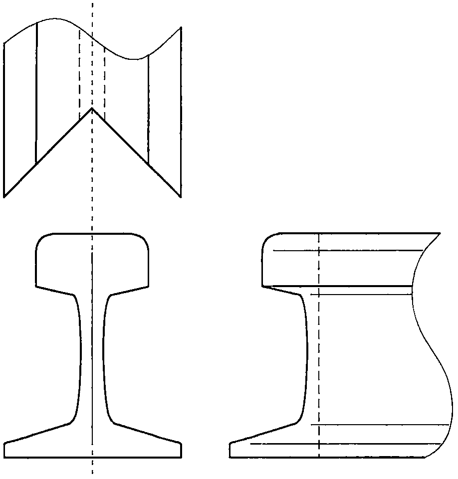
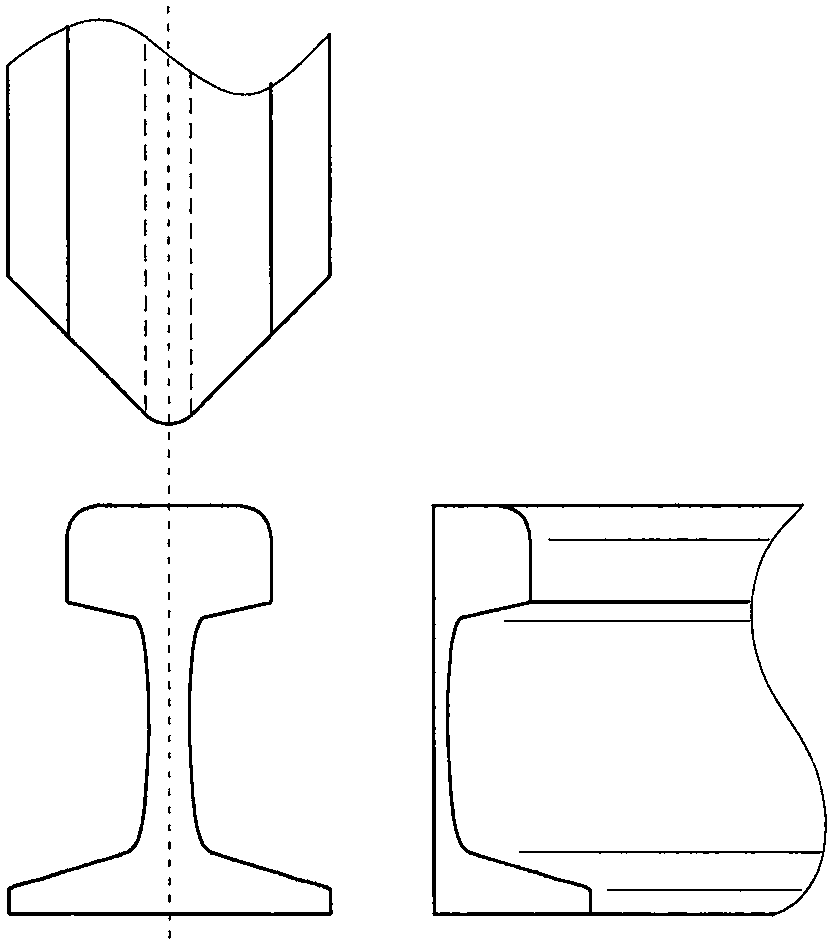
[0015] For two rails connected to each other, follow the figure 1 with figure 2 Cut as shown. After fixing the cutting equipment and the rail, adjust the angle of the cutting tool, and cut from both sides of the rail to the center of the rail, so that the sharp corner is just on the center line of the rail surface. The included angle between the cutting lines on both sides and the centerline of the longitudinal axis of the rail should be the same.

[0016] Grinding equipment is used to grind the sharp corner of the protruding end of the rail to eliminate the sharp corner.

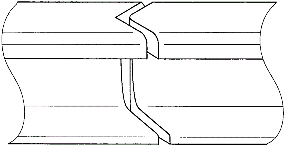
[0017] according to image 3 As shown, the protruding and concave parts of the two sections of rails are docked, appropriate rail gaps are reserved, and insulating materials are installed to ensure that the centerlines of the two sections of rails are consistent. Drill holes and clamp the rails with fishplates...


PUM


Abstract

The invention provides a steel rail assembly suitable for a wheeltrack traveling mode and suitable for state-owned railways, urban rails and traveler and goods transportation routes of large-size factories and mines in a wheeltrack transport mode. The steel rail assembly comprises at least two steel rails of which the ends are connected. The mutually connected ends of the two steel rails are cut in a '<' shape, so that an inwards concave triangular notch is formed in the rail surface of one steel rail, a corresponding outwards triangular convex part is formed on the rail surface of the other steel rail, and the <-shaped parts of the two steel rails are in butt joint. According to the novel steel rail assembly, continuous transition of wheel treads on the steel rails can be achieved so that impact force, shock and noise pollution can be reduced.

Description

technical field [0001] The invention provides a steel rail assembly suitable for the running mode of the wheel and the rail. Background technique [0002] Wheel-rail transportation is a common mode of transportation, widely used in passenger and cargo transportation of state-owned railways, urban rails and large factories and mines. At present, the connection methods between rails generally adopt metal welding and direct butt clamping methods. The first method is generally applied to the main line to ensure the continuity of the rails. The second method is easier to install and maintain. It is still widely used in turnout sections such as stations, section yards, low-speed lines or remote areas. [0003] The current butt joint clamping method is to join two vertically cut rail longitudinal sections, leaving a rail gap of about 1 cm in the middle to accommodate thermal expansion and contraction caused by temperature changes. According to the requirements of the track circui...

Claims


Application Information

Patent Timeline
IPC IPC(8): E01B5/04
CPCE01B5/04
Inventor 吴明桓
Owner 吴明桓
Why Eureka
Try Eureka