
A method of foundation pit support

A technology for foundation pit support and support piles, applied in excavation, foundation structure engineering, construction, etc., can solve the problems of difficult adaptation and high deformation requirements of support structures, and achieve the effect of small horizontal displacement and reduced length

Active Publication Date: 2021-03-16
TIANJI COAL CHEM IND GROUP
View PDF7 Cites 0 Cited by
  • Summary
  • Abstract
  • Description
  • Claims
  • Application Information

AI Technical Summary

Problems solved by technology

[0002] The foundation pit support in construction engineering is used for temporary foundation pit support of new projects under general geological conditions (the service life does not exceed 2 years), and the common ones are gravity retaining wall, buttress retaining wall and soil nail wall , cement-soil walls, lattice-type anchor retaining walls, pile-row anchor retaining walls, etc., when the foundation pit of a new project is close to existing buildings and structures, because of its high requirements for the deformation of the supporting structure , and it is not allowed to disturb the foundation soil layer of the existing buildings and structures, the above-mentioned foundation pit support methods are difficult to adapt to the foundation edge of the existing buildings and structures with the same service life as the existing buildings and structures. permanent foundation pit support

Method used


Image

  • A method of foundation pit support
  • A method of foundation pit support
  • A method of foundation pit support

Examples


Embodiment 1

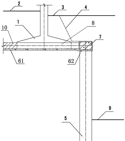
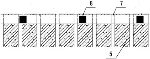
[0025] Such as figure 1 , 2 , as shown in 3,

[0026] 1. Measurement and setting out: at the proposed site, according to the foundation pit support requirements, carry out the construction site measurement and setting out, and determine the specific position of the supporting pile working face and the excavation sideline of the foundation pit 4;

[0027] Excavation site: Excavate the earthwork above the supporting pile working face, level the site according to relevant requirements, and mark the center line of the pile position;

[0028] Pile driver drilling in place: transport the pile driver to the construction site, and carry out drilling operations according to the construction sequence;

[0029] Lower reinforcement cage: tie and roll the steel bars in the support piles, and place them in the drilled support pile holes;

[0030] Pouring concrete for supporting piles: according to the regulations, pour concrete into the hole of supporting pile 5 from the bottom of the ho...

Embodiment 2

[0041] A foundation pit support method, comprising the following steps,

[0042] 1. On the proposed site, according to the support requirements, carry out the survey and setting out of the construction site, determine the specific position of the working face of the support piles and the excavation sideline of the foundation pit, and drive the support piles;

[0043] 2. Clean up the pile head, and remove the excess concrete within the range of the pile top as a crown beam and the concrete that does not meet the compactness requirements;

[0044] 3. In the existing buildings and structures, according to the original construction drawings of the foundation and combined with the actual situation on the site, determine the position of the caps of the existing buildings and structures, and determine the position of a tension beam on both sides of the caps,

[0045] 4. Excavate the foundation groove of the beam,

[0046] 5. Texturize the contact surface of existing buildings and st...


PUM


Abstract

The invention provides a foundation pit supporting method. The method combining an original foundation with straining beams and supporting piles is adopted. One sides of the supporting piles abut against the outer edge of the foundation of an existing building / structure, and a vertical foundation pit is located on the other sides of the supporting piles. The lower portions of the supporting piles are fixedly embedded in a soil layer of the foundation pit and serve as elastic supports. The upper portions of the supporting piles are anchored in a top beam and serve as hinged supports. Pile bodies of the supporting piles bear active earth pressure transferred from the soil layer below the bottom face of the foundation. By the adoption of the foundation pit supporting method, permanent foundation pit supporting is achieved on the foundation edge of the existing building / structure, when the construction space is small, a supporting structure can meet the deformation requirements, and safe and normal application of the existing building / structure is guaranteed.

Description

technical field [0001] The invention belongs to the field of construction engineering, and in particular relates to a foundation pit supporting method. Background technique [0002] The foundation pit support in construction engineering is used for temporary foundation pit support of new projects under general geological conditions (the service life does not exceed 2 years), and the common ones are gravity retaining wall, buttress retaining wall and soil nail wall , cement-soil walls, lattice-type anchor retaining walls, pile-row anchor retaining walls, etc., when the foundation pit of a new project is close to existing buildings and structures, because of its high requirements for the deformation of the supporting structure , and it is not allowed to disturb the foundation soil layer of the existing buildings and structures, the above-mentioned foundation pit support methods are difficult to adapt to the foundation edge of the existing buildings and structures with the same...

Claims


Application Information

Patent Timeline
Patent Type & Authority Patents(China)
IPC IPC(8): E02D17/04
CPCE02D17/04
Inventor 徐国明王明明崔健刚牛得朝张中旺张栓胜牛国明黄海燕
Owner TIANJI COAL CHEM IND GROUP
Learn More