
Vortex end outlet structure with core

An outlet structure, vortex end technology, applied in engine components, machines/engines, mechanical equipment, etc., can solve the problem of no increase or decrease in vortex end efficiency, and achieve the effects of simple and reasonable structure, improved overall efficiency, and low manufacturing costs.

Inactive Publication Date: 2017-02-15
WUXI CUMMINS TURBO TECH
View PDF6 Cites 0 Cited by
  • Summary
  • Abstract
  • Description
  • Claims
  • Application Information

AI Technical Summary

Problems solved by technology

However, due to the existence of the diffuser, the wake area at the center of the turbine outlet is also enlarged, resulting in no improvement in the efficiency of the entire turbine tip, or even a decrease

Method used


Image

  • Vortex end outlet structure with core
  • Vortex end outlet structure with core
  • Vortex end outlet structure with core

Examples


Embodiment Construction

[0017] The specific embodiments of the present invention will be further described below in conjunction with the accompanying drawings.

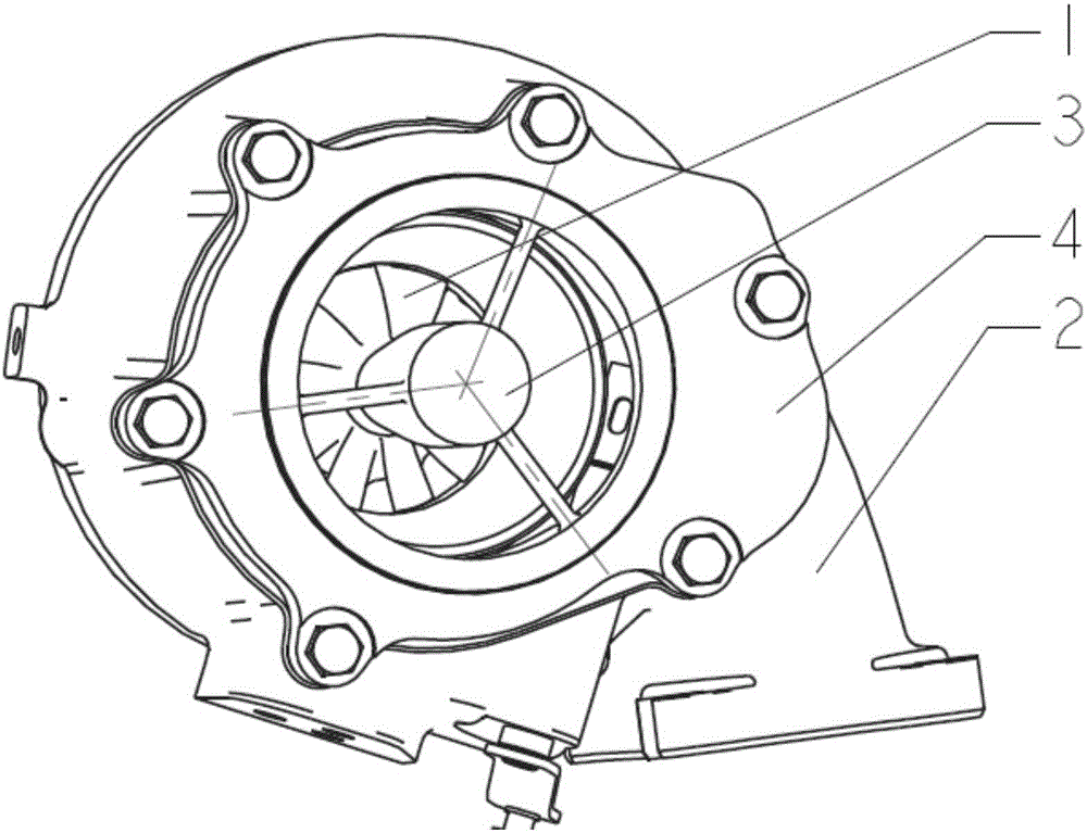
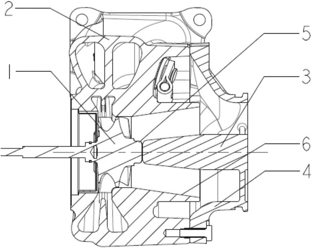
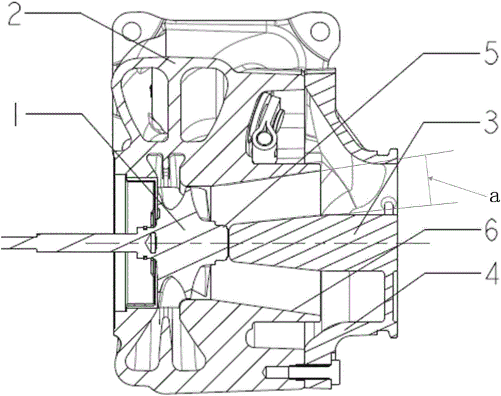
[0018] Figure 1~3 Among them, including the turbine 1, the turbine shell 2, the core 3, the transition joint 4, the turbine shaft 5, the turbine shell outlet 6, the angle a formed by the core outer diameter wall profile and the turbine shell outlet inner diameter wall profile on the plane passing the turbine shell axis Wait.

[0019] Such as Figure 1~3 As shown, the present invention is a cored vortex end outlet structure, including a turbine casing 2, the inner cavity of the turbine casing 2 is provided with a turbine 1 that can rotate around the axis of the turbine casing, and the casing of the turbine casing 2 is provided with a turbine Shell outlet 6, core 3 is arranged at the center of turbine shell outlet 6, turbine shaft 5 is integrated on turbine 1, there is a gap between core 3 and turbine shaft 5, core 3 is integrated on transi...


PUM


Abstract

The invention belongs to the technical field of engine turbocharging, and relates to a vortex end outlet structure with a core. The vortex end outlet structure with the core comprises a turbine shell, wherein a turbine capable of rotating around the axis of the turbine shell is arranged in an inner cavity of the turbine shell; a turbine shell outlet is formed in a shell body of the turbine shell; the core is arranged on the center position of the outlet of the turbine shell; a turbine shaft is integrated on the turbine; a gap is formed between the core and the turbine shaft; and the core is integrated on a transition joint or the turbine shell. The vortex end outlet structure with the core is simple and reasonable in structure, and is low in producing and manufacturing cost; and one core is additionally arranged on the center position of the vortex end outlet so that integral efficiency of the vortex end can be improved.

Description

technical field [0001] The invention belongs to the technical field of engine turbocharging, and relates to a cored vortex end outlet structure. Background technique [0002] A turbocharger is actually an air compressor that compresses air to increase intake air. It uses the inertial momentum of the exhaust gas discharged from the engine to drive the turbine in the turbine housing, and the turbine drives the coaxial impeller, which presses the air sent by the air filter pipe to pressurize it into the cylinder. When the engine speed increases, the exhaust gas discharge speed and the turbine speed also increase synchronously, and the impeller compresses more air into the cylinder, and the pressure and density of the air increase to burn more fuel. Increase the fuel volume and adjust the engine speed accordingly. , the output power of the engine can be increased. [0003] A turbocharger is generally composed of three parts: a vortex end, a pressure end and an intermediate bod...

Claims


Application Information

Patent Timeline
IPC IPC(8): F01D25/24
CPCF01D25/24
Inventor 高同军
Owner WUXI CUMMINS TURBO TECH
Features
  • Generate Ideas
  • Intellectual Property
  • Life Sciences
  • Materials
  • Tech Scout
  • Unparalleled Data Quality
  • Higher Quality Content
  • 60% Fewer Hallucinations
Learn More