
Automatic grease-injection device of bearing

A grease injection device and automatic technology, which is applied in the direction of engine components, engine lubrication, lubricating parts, etc., can solve problems affecting the grease lubrication effect, dry friction, pollution of the environment, etc., achieve less labor costs and improve grease injection efficiency Effect

Inactive Publication Date: 2017-02-15
湖南天天特训教育咨询有限公司
View PDF5 Cites 8 Cited by
  • Summary
  • Abstract
  • Description
  • Claims
  • Application Information

AI Technical Summary

Problems solved by technology

[0002] With the development of the times, people's living standards continue to improve, and industrialization and intelligence are also constantly innovating and developing. Bearings are commonly used transmission components in the field of industrial equipment and are widely used in various equipment. Bearings are a precision Mechanical basic parts, according to the requirements of the product, the bearing must be filled with a certain amount of grease before leaving the factory. During the grease injection process of the bearing, the grease needs to be injected into the ball between the inner and outer rings of the bearing. The existing grease injector There are many problems in the grease injection process. Too little grease injection will easily cause lack of grease or dry friction, which will affect the service life of the bearing; too much grease injection will cause the temperature of the bearing to rise, resulting in grease leakage, which pollutes the environment. , and cause waste. Usually, the oil pump is used to extract grease into the bearing. Air may be mixed in during the extraction process to form air bubbles, thereby affecting the lubrication effect of the grease. Therefore, it is necessary to improve the existing grease injection device to solve the above problems. The problem

Method used


Image

  • Automatic grease-injection device of bearing
  • Automatic grease-injection device of bearing

Examples


Embodiment Construction

[0012] The technical solutions in the embodiments of the present invention will be clearly and completely described below in conjunction with the accompanying drawings in the embodiments of the present invention. Obviously, the described embodiments are only a part of the embodiments of the present invention, rather than all the embodiments. Based on the embodiments of the present invention, all other embodiments obtained by those of ordinary skill in the art without creative work shall fall within the protection scope of the present invention.

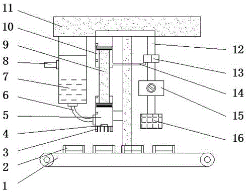
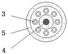
[0013] See Figure 1-2 , An embodiment provided by the present invention: an automatic grease injection device for bearings, comprising a transmission belt 1, a grease outlet tube 3, a grease storage tank 7, a T-shaped bracket 11 and an air pressure regulating valve 15. A bearing is fixed above the transmission belt 1 Slot 2, the conveyor belt 1 is used to convey the bearings to be greased. One side of the transmission belt 1 is provided...


PUM


Abstract

The invention discloses an automatic grease-injection device of a bearing. The automatic grease- injection device of the bearing comprises a driving belt, grease discharging thin pipes, a grease storing box, a T-shaped supporting frame and an air pressure adjusting valve. Bearing grooves are fixedly arranged on the driving belt, the T-shaped supporting frame is arranged on one side of the driving belt, and an upper piston bucket is arranged on one side of the bottom of a cross beam of the T-shaped supporting frame. The upper piston bucket is connected with a lower piston bucket through an inner double-end piston rod, a pneumatic pump is connected with the lower portion of an electromagnetic valve, and the air pressure adjusting valve is arranged in the middle position between the electromagnetic valve and the pneumatic pump. According to the automatic grease-injection device of the bearing, the bearing is subjected to grease injection by combination of automatic transmission and quantitative grease injection. The driving belt can enable the grease injection of the bearing to be streamlined, grease-injection efficiency is improved, and manual cost is reduced. The grease discharging thin pipes distributed in a ring shape, an infrared detector and the air pressure adjusting valve can enable fat to be injected between the inner ring and the outer ring of the bearing evenly, accurately and quantitatively, so that a reject ratio of the grease injection is reduced.

Description

Technical field [0001] The invention relates to the technical field of bearing grease injection equipment, in particular to an automatic bearing grease injection device. Background technique [0002] With the development of the times, people’s living standards continue to improve, and industrialization and intelligence are constantly innovating and developing. Bearings are commonly used transmission components in the field of industrial equipment and are widely used in various equipment. Bearings are a kind of precision Mechanical basic parts, according to the requirements of the product, the bearing must be filled with a certain amount of grease before leaving the factory. During the grease injection process of the bearing, the grease needs to be injected into the balls between the inner and outer rings of the bearing. The existing grease injector There will be many problems in the process of grease injection. Too little grease injection will easily cause grease shortage or dry ...

Claims


Application Information

Patent Timeline
Patent Type & Authority Applications(China)
IPC IPC(8): F16N37/00
CPCF16N37/003F16N2270/20
Inventor 颜伟吴彦玉
Owner 湖南天天特训教育咨询有限公司
Learn More