Light bar and light guide plate assembling jig

A technology for assembling fixtures and light guide plates, which is applied in the directions of light sources, lighting devices, and light source fixing. Effect

Pending Publication Date: 2017-02-15
BOE OPTICAL SCI & TECH +1
View PDF8 Cites 2 Cited by
  • Summary
  • Abstract
  • Description
  • Claims
  • Application Information

AI Technical Summary

Problems solved by technology

However, because the LED light bar is too soft and light, the assembly fixtures in the prior art can no longer maintain the flat positioning of the light bar, and the light bar is easy to bend or fall out of the assembly fixture, resulting in low assembly efficiency and precision, resulting in a light guide plate Poor connection with the LED light bar, there is a gap between the LED light bar and the light guide plate, which affects the brightness of the backlight module

Method used


Image

  • Light bar and light guide plate assembling jig
  • Light bar and light guide plate assembling jig
  • Light bar and light guide plate assembling jig

Examples


Embodiment Construction

[0040] The following will clearly and completely describe the technical solutions in the embodiments of the present invention with reference to the accompanying drawings in the embodiments of the present invention. Obviously, the described embodiments are only some, not all, embodiments of the present invention.

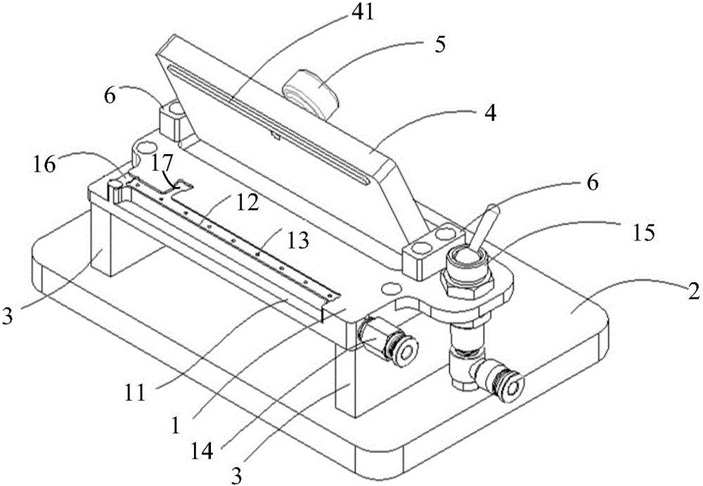
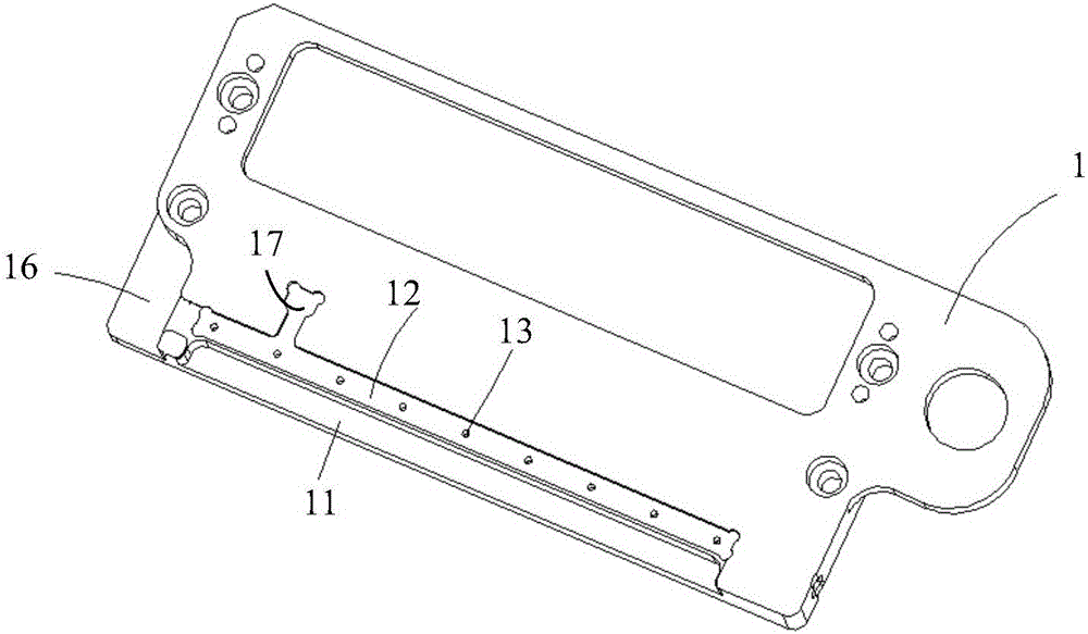
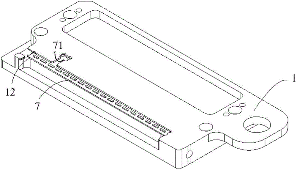
[0041] Such as figure 1 , figure 2 , image 3 and Figure 4 shown, where: figure 1 Schematic diagram of the structure of the light bar and light guide plate assembly jig provided by the embodiment of the present invention; figure 2 Schematic diagram of the structure of the bearing platform provided by the embodiment of the present invention; image 3 A schematic structural diagram of the assembly of the carrying platform and the light bar provided by the embodiment of the present invention; Figure 4 A schematic diagram of the pressed structure of the light bar and the light guide plate provided by the embodiment of the present invention; the present invention...


PUM


Abstract

The invention relates to the technical field of display device manufacturing, and discloses a light bar and light guide plate assembling jig. The light bar and light guide plate assembling jig comprises a bearing table and a pressing plate; the bearing table is provided with a positioning assembling groove for containing a light bar and a light guide plate, and a step protrusion used for supporting the light bar is arranged in the positioning assembling groove and is provided with an attraction unit used for attracting the light bar; and the pressing plate is rotationally connected with the bearing table and used for tightly pressing a pasting layer of the light bar and the light guide plate. When the light bar and light guide plate assembling jig is used, the light bar and the light guide plate can be positioned through the positioning assembling groove, the light bar can be tightly attached to the light entering side of the light guide plate through the pressing plate, and the attraction unit is arranged so that the light bar can be smoothly fixed to the step protrusion. By means of the light bar and light guide plate assembling jig, the phenomenon of light bar bending and the phenomenon that the light bar is separated from the light bar and light guide plate assembling jig are avoided, and the accuracy of light bar and light guide plate assembling is improved.

Description

technical field [0001] The invention relates to the technical field of display device preparation, in particular to a fixture for assembling a light bar and a light guide plate. Background technique [0002] As display products become more and more ultra-thin, the light guide plate and LED light bar in the backlight module of the display device are getting thinner and thinner, which will make the light guide plate and LED light bar softer and easier to damage. Assembly process requirements are higher. [0003] During the process of assembling the LED light bar and the light guide plate, the LED light bar is bonded with an adhesive layer for bonding and connecting with the light guide plate. During bonding, the LED light bar is fixedly connected with the light guide plate through the adhesive layer. However, because the LED light bar is too soft and light, the assembly fixtures in the prior art can no longer maintain the flat positioning of the light bar, and the light bar i...

Claims


Application Information

Patent Timeline
Patent Type & Authority Applications(China)
IPC IPC(8): F21V19/00F21V17/10F21Y115/10F21Y103/10
CPCF21V17/10F21V19/0035
Inventor 张庆栾庆军王挺周玉华
Owner BOE OPTICAL SCI & TECH
Why Eureka
Try Eureka