Flip direct falling type optical chip module testing socket

A technology for testing optical chips and modules, which is applied in the direction of measuring devices, measuring electrical variables, and measuring device casings, and can solve problems affecting the position of the chip lens hole, chip shift, and affecting the test results of high-pixel optical chips.

Active Publication Date: 2017-02-15
WENZHENG COLLEGE OF SOOCHOW UNIV
View PDF10 Cites 8 Cited by
  • Summary
  • Abstract
  • Description
  • Claims
  • Application Information

AI Technical Summary

Problems solved by technology

However, since the flap is flipped, when the pressure plate and the chip first come into contact, they can only touch a part of the side of the chip, so that the relative sliding between the pressure plate and the chip may cause the chip to shift, affecting the chip and the chip fixed on the upper cover. The position between the upper lens holes directly affects the test results of high-pixel optical chips

Method used


Image

  • Flip direct falling type optical chip module testing socket
  • Flip direct falling type optical chip module testing socket
  • Flip direct falling type optical chip module testing socket

Examples


Embodiment Construction

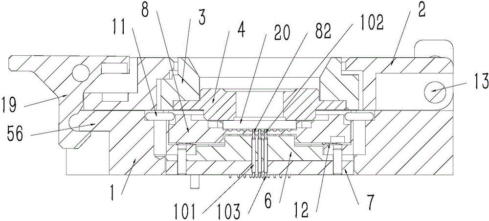
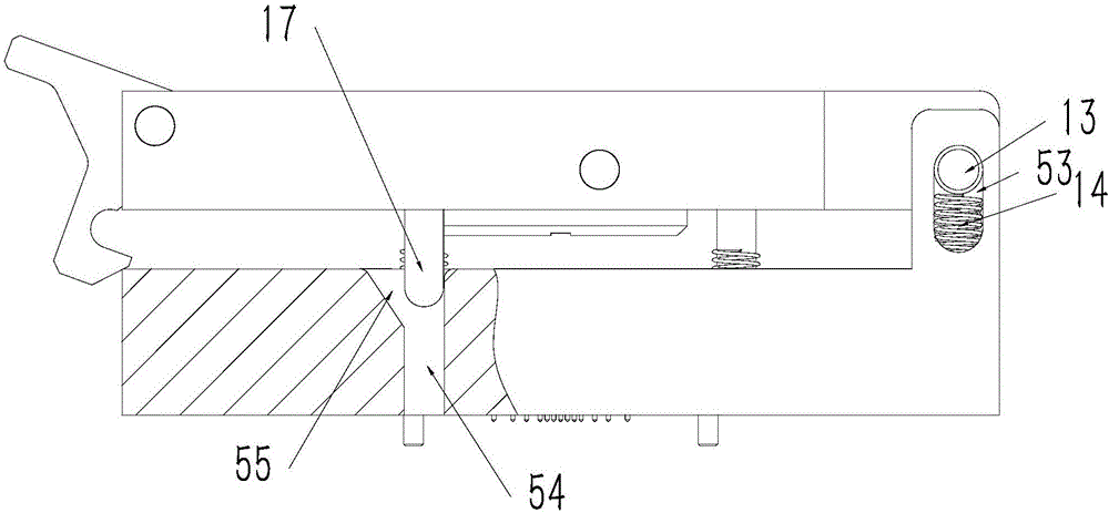
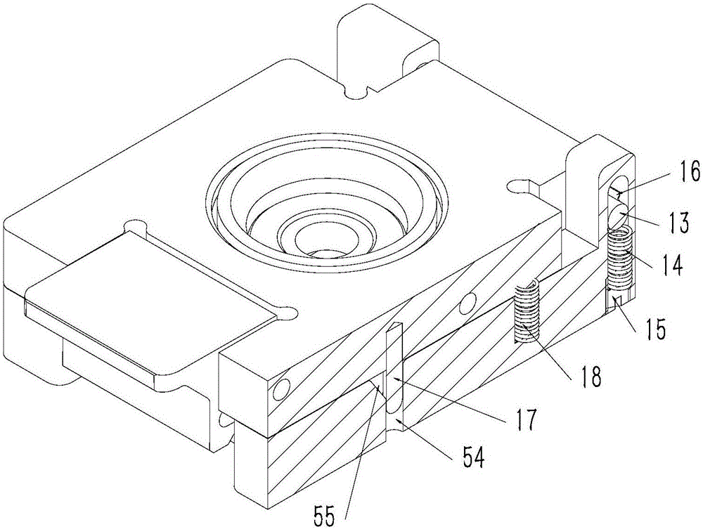
[0023] see figure 1 , 2 , The flip-down type manual optical chip module test socket shown in 5 mainly includes a base 1, an upper cover 2 flipped and connected to the base, a screw cover 3, a pressure plate 4, a main board 6, a retaining plate 7, a floating plate 8, Probe 10.

[0024] The probe 10 belongs to the prior art, and includes a needle bar 101 and an upper needle head 102 and a lower needle head 103 floatingly connecting the two ends of the needle bar.

[0025] A base hole 52 with a step 51 is formed on the base 1. The main board 6 is fixed at the bottom of the base hole 52, and the holding plate 7 is fixed on the base below the main board. There is a floating plate 8 in the top of the base hole 52 . The periphery of the bottom of the floating plate 8 is arranged on the upper part of the step 51 floating up and down through four floating springs 12. The floating plate is located above the main board. There is a chip slot 81 for placing the optical chip module 20 on...


PUM


Abstract

The invention aims to provide a flip direct falling type optical chip module testing socket, the relative sliding of a pressing plate and a chip is avoided, and the positioning precision of the chip is improved. The flip direct falling type optical chip module testing socket comprises a base, an upper cover, and a probe. The probe comprises a probe rod and needles. A motherboard and a maintaining plate under the motherboard are fixed on the base. A floating plate above the motherboard is arranged on the base in an up and down floating way. The upper part of floating plate is provided with a chip groove. The bottom of the chip groove is provided with a needle hole. The probe rod of the probe is fixed by the maintaining plate and the motherboard. The needle of the upper end goes through the motherboard and extends upward into the needle hole. The needle of the lower end goes through the maintaining plate and extends downward. The upper cover is connected to a rotation cover. The pressing plate is fixed under the rotation cover. The upper cover is connected to a pin shaft. The base is provided with a waist-shaped pin hole whose bottom is provided with an upward push spring. The side wall of the waist-shaped pin hole is provided with a limit spring. When a downward external force is applied to the pin shaft and the pin shaft exceeds the limit spring, the limit spring returns to a normal state, and the pin shaft is maintained at the lower part of the waist-shaped hole.

Description

technical field [0001] This technology is a socket used for testing optical chip modules. Background technique [0002] The optical camera chip (CIS) and its camera module (CMOS) are widely used in industrial, medical and consumer fields. With the requirements of end users for image processing and the development of high-pixel image acquisition and analysis technology, this product has gradually replaced the original glass optical lens in many fields. [0003] The tens of millions of optical chip modules is a major development trend in the CIS and CMOS industries. At present, this kind of chip is mainly used in satellites, high-altitude reconnaissance aircraft and high-pixel smart cameras. With the product's packaging and testing process becoming more and more mature, the trend of application in high-definition cameras, surveillance cameras, mobile phone cameras and computer cameras will be unstoppable. [0004] In China, although a 12-megapixel optical chip module appeare...

Claims


Application Information

Patent Timeline
Patent Type & Authority Applications(China)
IPC IPC(8): G01R1/04
CPCG01R1/0433G01R1/0466Y02E10/50
Inventor 刘鑫培
Owner WENZHENG COLLEGE OF SOOCHOW UNIV
Why Eureka
Try Eureka