Variable magnification optical system and imaging apparatus

An optical system and image-side technology, applied in optics, optical components, instruments, etc., can solve problems such as large curvature of the image plane and achieve high optical performance

Inactive Publication Date: 2017-02-15
FUJIFILM CORP
View PDF6 Cites 7 Cited by
  • Summary
  • Abstract
  • Description
  • Claims
  • Application Information

AI Technical Summary

Problems solved by technology

However, although the optical system described in Patent Document 1 has a h

Method used


Image

  • Variable magnification optical system and imaging apparatus
  • Variable magnification optical system and imaging apparatus
  • Variable magnification optical system and imaging apparatus

Examples


Embodiment 1

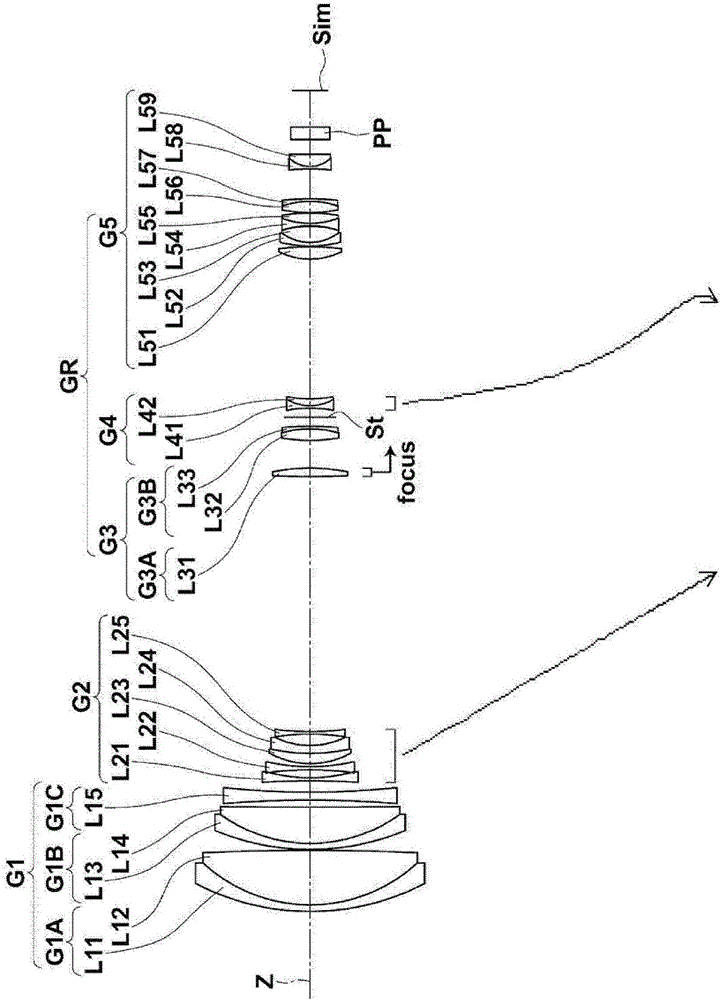
[0160] The lens of the variable power optical system of embodiment 1 constitutes as figure 1 , Figure 8 As shown, the illustration method is as above, so repeated descriptions are omitted here. As a group configuration, the variable power optical system of Example 1 is sequentially composed of the first lens group G1 with positive refractive power, the second lens group G2 with negative refractive power, and the third lens group with positive refractive power in order from the object side. G3, the aperture stop St, the fourth lens group G4 with negative refractive power, and the fifth lens group G5 with positive refractive power, wherein the third lens group G3 to the fifth lens group G5 constitute the follow-up lens group GR , the follow-up lens group GR adopts a composition with positive refractive power in the entire zoom range. When zooming from the wide-angle end to the telephoto end, the first lens group G1, the third lens group G3, the aperture stop St, and the fifth...

Embodiment 2

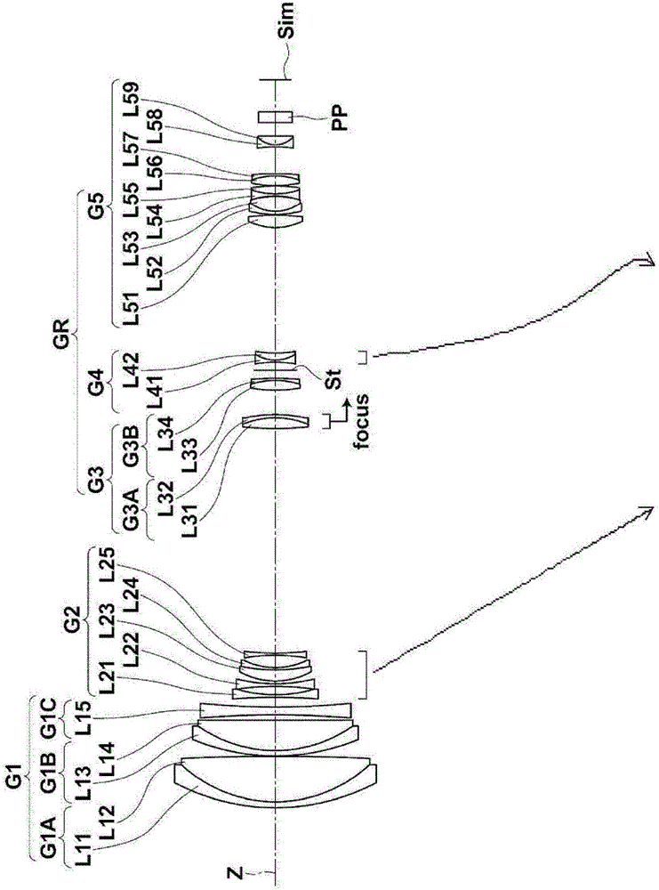
[0176] The lens of the variable power optical system of embodiment 2 constitutes as figure 2 shown. The group configuration of the variable power optical system of the second embodiment, the moving lens group and its moving direction during the variable power are the same as those of the variable power optical system of the first embodiment.

[0177] At the time of focusing, only a part of the third lens group G3 moves. The third lens group G3 is composed of a third lens group front group G3A having positive refractive power and a third lens group rear group G3B having positive refractive power in order from the object side. When focusing from an object at infinity to a short-distance object, the front group G3A of the third lens group moves from the object side to the image side, and the rear group G3B of the third lens group is fixed relative to the image plane Sim.

[0178] The first lens group G1 is composed of lenses L11 to L15 in order from the object side, and the se...

Embodiment 3

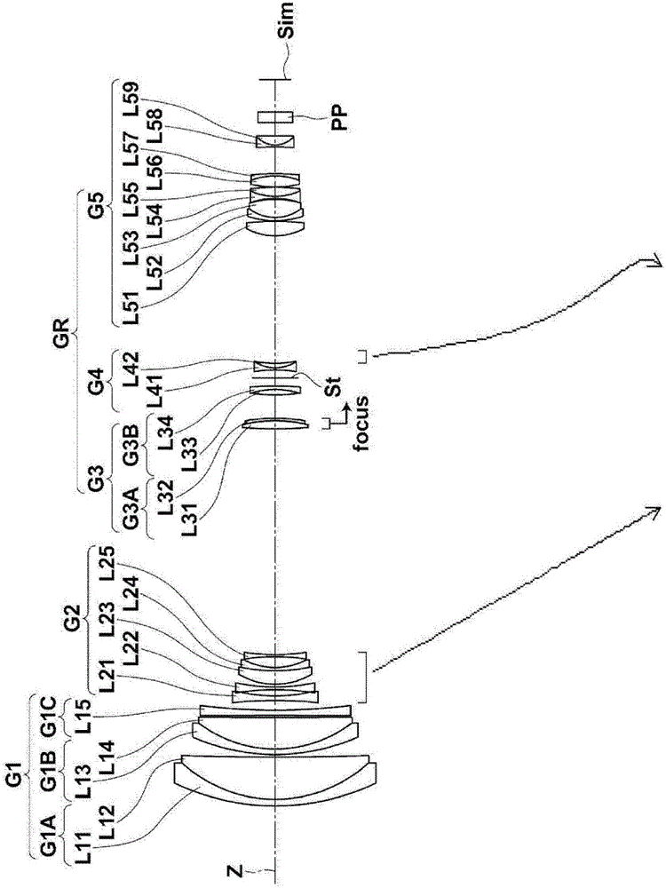
[0187] The lens of the variable power optical system of embodiment 3 constitutes as image 3 shown. The group configuration of the variable power optical system of the third embodiment, the moving lens group and its moving direction during the variable power are the same as those of the variable power optical system of the first embodiment.

[0188] At the time of focusing, only a part of the third lens group G3 moves. The third lens group G3 is composed of a third lens group front group G3A having positive refractive power and a third lens group rear group G3B having positive refractive power in order from the object side. When focusing from an object at infinity to a short-distance object, the front group G3A of the third lens group moves from the object side to the image side, and the rear group G3B of the third lens group is fixed relative to the image plane Sim.

[0189] The first lens group G1 is composed of lenses L11 to L15 in order from the object side, and the seco...


PUM


Abstract

A variable magnification optical system includes, in order from the object side: a positive first lens group (G1); a negative second lens group (G2); a positive third lens group (G3); a negative fourth lens group (G4); and a positive fifth lens group (G5). When changing magnification from the wide angle end to the telephoto end, the first and third lens groups are fixed with respect to an image formation plane, the second lens group moves toward the image side, the fourth lens group moves, and the distance between the fourth and fifth lens groups changes. A rearward lens group (GR) constituted by the third, fourth, and fifth lens groups has a positive refractive power throughout the variable magnification range. The transverse magnification ratio of the fourth lens group when focused on an object at infinity is negative throughout the variable magnification range.

Description

technical field [0001] The present invention relates to a variable magnification optical system and an imaging device, and particularly relates to a variable magnification optical system suitable for a long-distance surveillance camera, and an imaging device including the variable magnification optical system. Background technique [0002] Conventionally, surveillance cameras have been used for purposes such as theft prevention and recording, but the number of surveillance cameras installed has increased in recent years. As a lens system for a surveillance camera, it is preferable to use a variable power optical system when high versatility is desired. As a known variable power optical system, for example, there is a lens system as described in the following patent document 1: a first lens group G1 having a positive refractive power and a second lens group having a negative refractive power in order from the object side. G2, the third lens group G3 with positive refractive ...

Claims


Application Information

Patent Timeline
IPC IPC(8): G02B15/16G02B15/173
CPCG02B15/16G02B15/20G02B15/143105G02B27/0025G02B13/009
Inventor 富冈右恭长伦生
Owner FUJIFILM CORP
Why Eureka
Try Eureka