
Vegetation scene rendering method

A scene and vegetation technology, applied in the field of 3D scene rendering, to achieve the effect of improving the realism, expanding the projection area, and avoiding the sense of patchiness

Inactive Publication Date: 2017-02-15
BEIJING PIXEL SOFTWARE TECH
View PDF2 Cites 5 Cited by
  • Summary
  • Abstract
  • Description
  • Claims
  • Application Information

AI Technical Summary

Problems solved by technology

[0005] It can be seen that using the existing vegetation scene rendering method, the camera will have a patchy problem when observing the vegetation from certain angles

Method used


Image

  • Vegetation scene rendering method
  • Vegetation scene rendering method
  • Vegetation scene rendering method

Examples


Embodiment Construction

[0018] In order to make the purpose, technical solution and advantages of the present invention clearer, the present invention will be further described in detail below in conjunction with the accompanying drawings and specific embodiments.

[0019] The core idea of ​​the present invention is to simulate the characteristics of the outward divergence of the vegetation leaf surface, and to offset the top vertex of the square patch of the object to be rendered in the vegetation scene in the horizontal direction, that is, the angle of the offset is perpendicular to the patch, so that When observing the grass body from top to bottom, the projection of the grass body patch will be relatively large, so as to avoid the appearance of the patch.

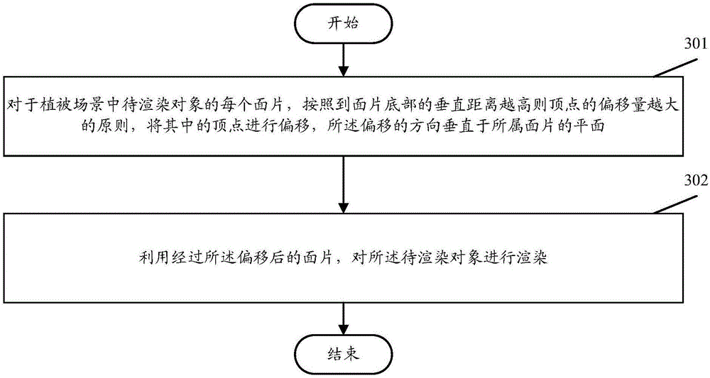
[0020] image 3 It is a schematic flow diagram of the method of the embodiment of the present invention, such as image 3 As shown, the rendering method embodiment of the vegetation scene mainly includes:

[0021] Step 301. For each patch of...


PUM


Abstract

The invention discloses a vegetation scene rendering method. The vegetation scene rendering method comprises steps that for each facet of a to-be-rendered object in a vegetation scene, vertex offset is carried out according to a principle that a vertical distance to a bottom portion of the facet is in direct proportion to offset amount of vertexes, and an offset direction is perpendicular to a plane of the facet; the facet after offset is utilized to render the to-be-rendered object. The method is advantaged in that a facet sense problem during scene rendering can be avoided, and rendering trueness is improved.

Description

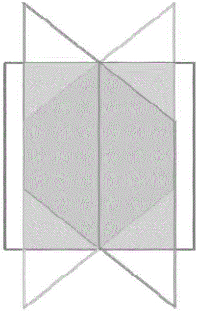
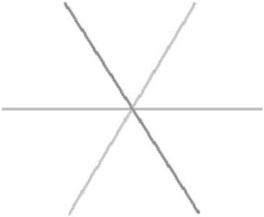
technical field [0001] The invention relates to a three-dimensional scene rendering technology, in particular to a vegetation scene rendering method. Background technique [0002] Rich vegetation can effectively enhance the realism of the scene. The procedural vegetation generation technology can use less storage space and use the powerful computing power of the CPU to generate grass meshes at runtime, and is widely used in graphics engines. [0003] In vegetation scenes, the generated vegetation is usually quite dense. In the traditional procedural vegetation generation scheme, a star grid formed by the intersection of three square patches is used (the angle between the patches is 60 degrees). , to simulate the appearance of vegetation clusters, such as figure 1 shown. When rendering, the texture of vegetation (such as grass) will be pasted on each patch. [0004] In the above vegetation scene rendering scheme, when the direction of the camera is close to parallel to th...

Claims


Application Information

Patent Timeline
Patent Type & Authority Applications(China)
IPC IPC(8): G06T15/00
CPCG06T15/005
Inventor 罗树权
Owner BEIJING PIXEL SOFTWARE TECH
Learn More