Driving apparatus, lens apparatus including the same, and imaging apparatus

a technology of driving apparatus and lens, applied in the direction of printers, instruments, cameras, etc., can solve the problem of large length of the unit in the driving direction, and achieve the effect of driving efficiency, driving amount and driving efficiency without reducing power outpu

Active Publication Date: 2017-05-16
CANON KK
View PDF5 Cites 3 Cited by
  • Summary
  • Abstract
  • Description
  • Claims
  • Application Information

AI Technical Summary

Benefits of technology

[0007]An object of the invention is made to solve the above-mentioned problem and to provide a linear vibration wave motor as a compact driving apparatus with no need to enlarge a projected area viewed from the pressing direction of driven member and without reducing a power output, driving efficiency and driving amount.
[0050]According to the invention, a linear vibration wave motor as a compact driving apparatus without reducing a power output, driving efficiency and driving amount and with no need to enlarge the projected area viewed from the pressing direction of driven member can be obtained.

Problems solved by technology

As a result, there has been a problem that a full length of unit in the driving direction becomes large.

Method used


Image

  • Driving apparatus, lens apparatus including the same, and imaging apparatus
  • Driving apparatus, lens apparatus including the same, and imaging apparatus
  • Driving apparatus, lens apparatus including the same, and imaging apparatus

Examples


embodiment 1

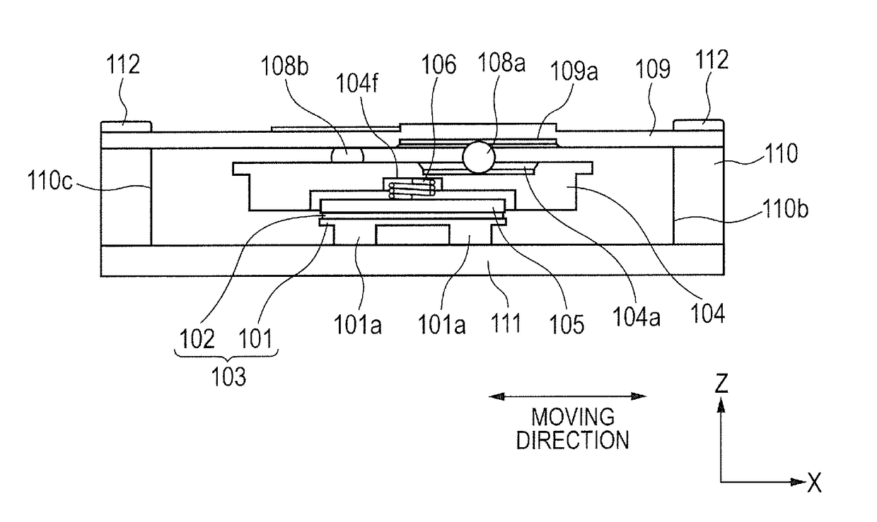
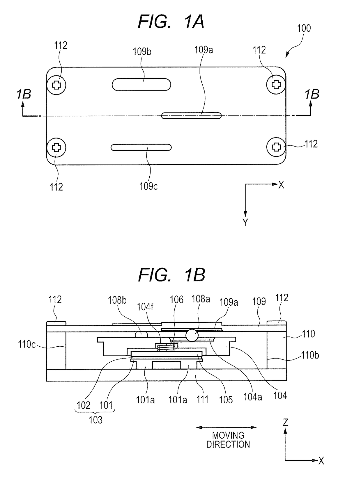
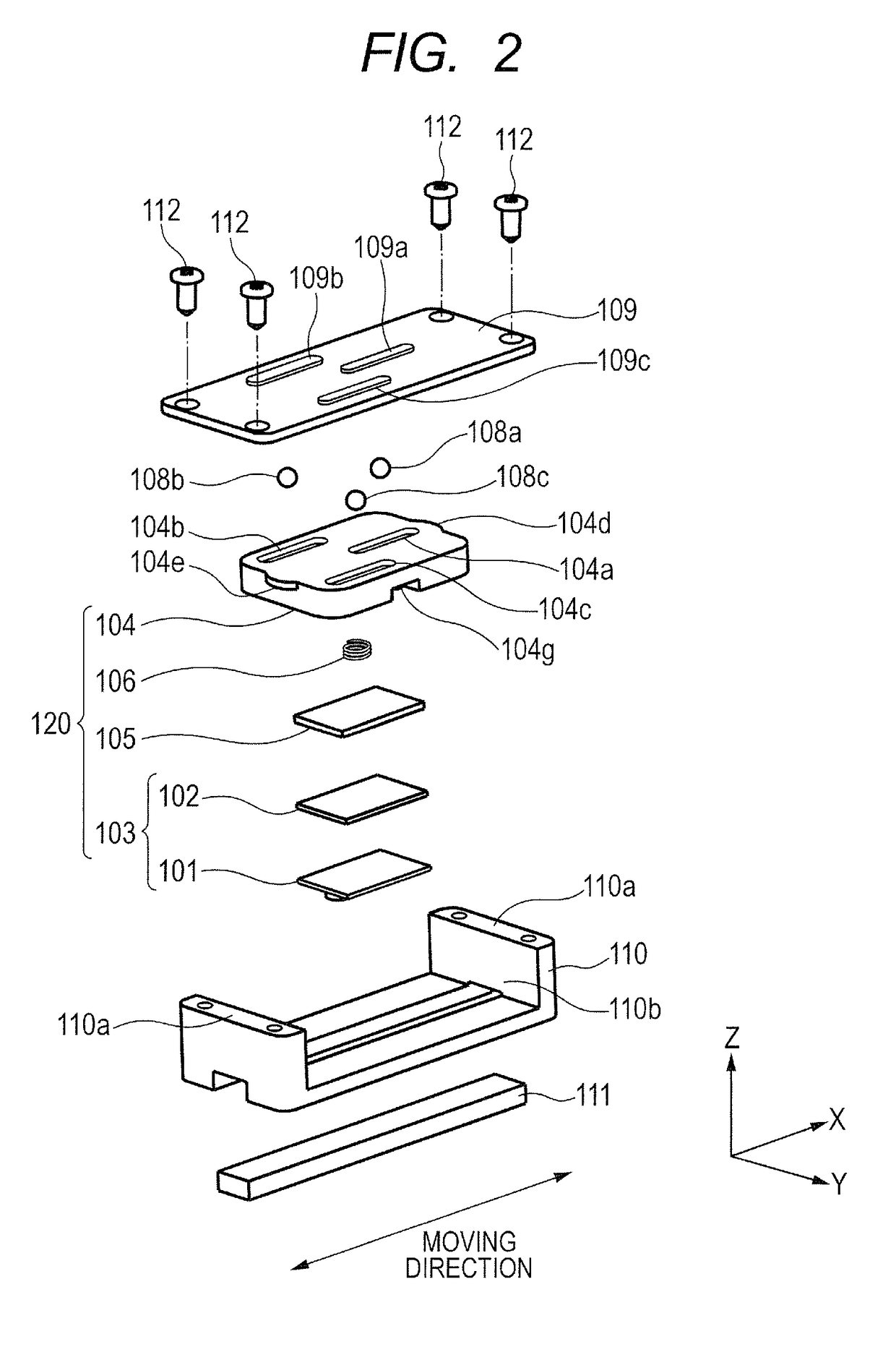
[0063]FIGS. 1A and 1B illustrate a linear vibration wave motor of embodiment 1 according to the invention, of which FIG. 1A is a plan view, and FIG. 1B is a cross sectional view taken along a line 1B-1B in FIG. 1A. FIG. 2 is an exploded perspective view illustrating a linear vibration wave motor of embodiment 1 according to the invention.

[0064]A linear vibration wave motor 100 of embodiment 1 of the invention has a longitudinal axis in an X-axis direction and is configured by each of the members to be described later. A piezoelectric element 102 is fixed on a vibrating plate 101 by a glue agent or the like, and a voltage is applied to the piezoelectric element 102 to excite vibration (vibration wave). It is noted that configuration of adhesion between the vibrating plate 101 and the piezoelectric element 102 is not limited as long as the adhesion is obtained. The vibrating plate 101 is further provided with a contact portion 101a, and the contact portion 101a is in pressed contact w...

embodiment 2

[0081]FIG. 4 is a plan view, viewed from the Z-axis direction, illustrating a linear vibration wave motor as a driving apparatus of embodiment 2 according to the invention. It is noted that a part of parts is not illustrated to facilitate the explanation.

[0082]In the figure, common numerals are assigned to members having common functions to those of embodiment 1. Further, explanation as to common configurations and functions to those of embodiment 1 is omitted.

[0083]In the embodiment, a vibrating plate 101 is provided with two contact portions 101a-1 and 101a-2, which are in pressed contact with a not illustrated friction member by a pressing portion including a spring 106. A line b connecting the centers of each of two contact portions 101a-1 and 101a-2 is parallel to an X-axis.

[0084]A pressing mechanism retaining member 104 is provided with three movable side guide portions 104a, 104b and 104c that are V-shaped grooves each having a V-shaped cross section. The movable side guide p...

embodiment 3

[0087]FIG. 5 is a plan view, viewed from the Z-axis direction, illustrating a linear vibration wave motor of embodiment 3 according to the invention. It is noted that a part of parts is not illustrated to facilitate the explanation.

[0088]In the figure, common numerals are assigned to members having common functions to those of embodiment 1. Further, explanation as to common configurations and functions to those of embodiment 1 is omitted.

[0089]In the embodiment, the vibrating plate 101 is provided with two contact portions 101a-1 and 101a-2, which are in pressed contact with a not illustrated friction member by a pressing portion including a spring 106. A line c connecting the centers of each of two contact portions 101a-1 and 101a-2 is arranged at a predetermined angle with respect to an X-axis.

[0090]A pressing mechanism retaining member 104 is provided with three movable side guide portions 104a, 104b and 104c that are V-shaped grooves each having a V-shaped cross section. The mov...


PUM


Abstract

A driving apparatus comprises a movable portion having movable side guide portions; a base portion having fixed side guide portions; a vibrator having a piezoelectric element; a friction member provided at one of the movable portion and the base portion; a pressing portion, provided at the other of the movable member and the base portion, for applying a pressing force to the vibrator; and rolling portions sandwiched between the movable side guide portions and the fixed side guide portions. The movable side guide portions and the fixed side guide portions extend with a predetermined length in a moving direction in which the movable portion is moved with respect to the base portion, and one of movable side guide portions is positioned within spacing in a direction orthogonal to the moving direction of a pair of movable side guide portions of the movable side guide portions.

Description

BACKGROUND OF THE INVENTION[0001]Field of the Invention[0002]The present invention relates to a driving apparatus, more specifically, to a linear driving type of vibration wave motor, called hereinafter linear vibration wave motor.[0003]Description of the Related Art[0004]In a conventional linear vibration wave motor, a high frequency voltage is applied to a piezoelectric element to vibrate a vibrator on which a piezoelectric element is fixed. Vibration of vibrator drives a sliding member pressed by the vibrator. Various attempts have been made to provide a compact type of linear vibration wave motors that are capable of maintaining high power output and enhancing driving efficiency.[0005]For example, in a linear vibration wave motor disclosed in Japanese Patent application Laid-open No. 2009-011099, a vibrator having a piezoelectric element is provided with two drivers abutted to a driven member and four rolling members between the driven member and a base member. And the four roll...

Claims


Application Information

Patent Timeline
Patent Type & Authority Patents(United States)
IPC IPC(8): G02B7/02H01L41/09H01L41/053G02B7/08G03B3/10
CPCH01L41/09G02B7/08G03B3/10H01L41/0536G03B2205/0061H02N2/0055H02N2/026H10N30/20H10N30/886
Inventor YAMANAKA, TAKUMI
Owner CANON KK
Why Eureka
Try Eureka