Light guide device

A light guide device and optical axis technology, applied in optics, optical components, instruments, etc., can solve problems such as the inability to determine the position of the reflector of the front-stage ray tracing unit, the difficulty in tracking the position of the light source, and the impact on the service life of the device. Time cost and financial cost, the adjustment process is simple and reliable, and the effect of reducing light attenuation

Inactive Publication Date: 2015-07-22
TIANJIN DINGRI TECH DEV CO LTD
View PDF4 Cites 3 Cited by
  • Summary
  • Abstract
  • Description
  • Claims
  • Application Information

AI Technical Summary

Problems solved by technology

[0005] This device has the following disadvantages: since the front-stage ray tracing unit rotates with the rear-stage ray-tracing unit, when adjusting the orientation of the latter-stage ray-tracing unit, the position of the front-stage ray-tracing unit is in a changing state, that is, it is impossible to determine the position of the front-stage ray-tracing unit. Therefore, it is difficult to track the position of the light source. It is necessary to continuously adjust the relative positions of the front and rear ray tracing units to achieve a suitable combination of positions to realize the change of the position of the light source. This continuous and repeated adjustment The process is quite complicated, difficult to control, and requires high calculation accuracy; and the mechanical structure adopted makes the installation of the two-stage unit require high installation accuracy, which reduces the yield; at the same time, it needs constant adjustment during use, which is easy to cause Wear of mechanical parts, affecting the service life of the entire device
In addition, because the distance between the reflector of the front-stage ray tracing unit and the reflector of the rear-stage ray tracing unit directly affects the incident width of light, and at the same time, when tracing the position of the light source, there is a central blind area G, that is, if the light source is in the central blind area G When , the device cannot track the light source, making it limited in the process of light source collection

Method used


Image

  • Light guide device
  • Light guide device
  • Light guide device

Examples


Embodiment Construction

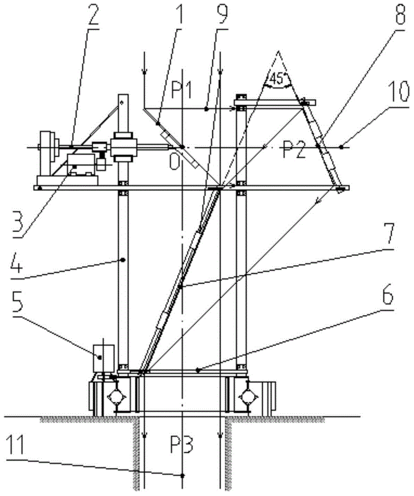
[0046] The present invention will be further described in detail below in conjunction with the accompanying drawings and specific embodiments.

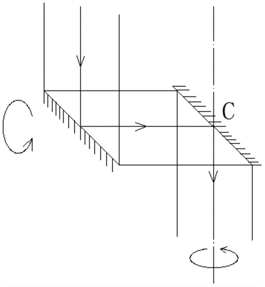
[0047] like image 3 As shown, the light guiding device of the present invention includes a primary rotating reflection assembly 13, a secondary rotating reflection assembly 14 and a rotation control assembly. Among them, the first level and the second level here are only used to distinguish two groups of rotating reflection components, and there is no sequential rotation relationship.

[0048] The rotation control component is used to respectively control the rotation of the primary rotary reflection component 13 and the secondary rotary reflection component 14 around their respective rotation axes 10, 11, wherein the rotation axes of the two are perpendicular to each other and intersect at the intersection point, that is, point O , the primary rotating reflective assembly 13 is disposed on the secondary rotating reflective assembly...


PUM


Abstract

The invention provides a light guide device comprising a first stage rotary reflection component, a second stage rotary reflection component and a rotating control component. The rotating control component is used for controlling the first stage rotary reflection component and the second stage rotary reflection component to rotate around the own rotary shafts respectively or controlling the first stage rotary reflection component to rotate with the second stage rotary reflection component, and the rotary shafts are perpendicular to each other and are crossed in a crossed point; the optical axis of a final light beam and the optical axis of an incident light beam are perpendicular to the optical axis of a first reflection light, and the optical axis of the final light beam and the optical axis of the first reflection light penetrate the crossed point. The light guide device is convenient to install and is capable of being adaptive to the change of positions of the light source or target flexibly and positioning and tracking the light source or target, the light source acquiring efficiency is improved, and light weakening is avoided effectively.

Description

technical field [0001] The invention relates to the technical field of optical equipment, in particular to a light guiding device. Background technique [0002] Light is a specific band of the electromagnetic spectrum. The light that people see comes from luminous substances in the universe (such as stars) or by means of devices that generate light, including incandescent bulbs, fluorescent tubes, lasers, fireflies, etc. Light is closely related to people's lives. Light can provide illumination for people, and light also has energy. Light energy can be used to provide heat for people, and can also be converted into other forms of energy. Therefore, the collection and utilization of light is very important . [0003] For example, it is well known that most of the energy sources on the earth come directly or indirectly from solar energy, including wind energy, water energy, biomass energy and various fossil energy sources. Human beings, animals and plants on the earth also d...

Claims


Application Information

Patent Timeline
Patent Type & Authority Applications(China)
IPC IPC(8): G02B26/08G02B17/06
Inventor 于颖杰
Owner TIANJIN DINGRI TECH DEV CO LTD
Why Eureka
Try Eureka