Reversing switch of electric tool

A technology of electric tools and reversing switches, which is applied in the direction of electric switches, circuits, electrical components, etc., can solve the problems of difficult assembly of reversing switches, low reliability of switches, high defect rate, etc., achieve low cost, improve reliability, and contact good effect

Active Publication Date: 2017-02-15
ZHANGJIAGANG HUAJIE ELECTRONICS
View PDF4 Cites 2 Cited by
  • Summary
  • Abstract
  • Description
  • Claims
  • Application Information

AI Technical Summary

Problems solved by technology

[0002] The reversing switch of commonly used electric tools includes a button, a base, a push rod set in the base and connected to the button, a reversing handle set inside the base, a lever set outside the base, and a connection reversing The connecting shaft of the shifting handle and the shifting rod, the reversing terminal group arranged in the base, the first reversing moving contact and the second reversing moving contact that are clamped on the reversing handle and contact with the reversing base The reversing terminals are assembled on the base respectively. The reversing switch with this structure is difficult to assemble, with high defect rate and high cost. Poor contact is prone to occur during reversing operation, resulting in low reliability of the switch.

Method used


Image

  • Reversing switch of electric tool
  • Reversing switch of electric tool
  • Reversing switch of electric tool

Examples


Embodiment Construction

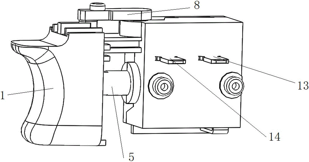
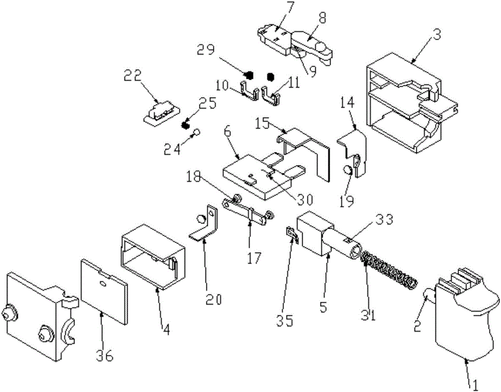
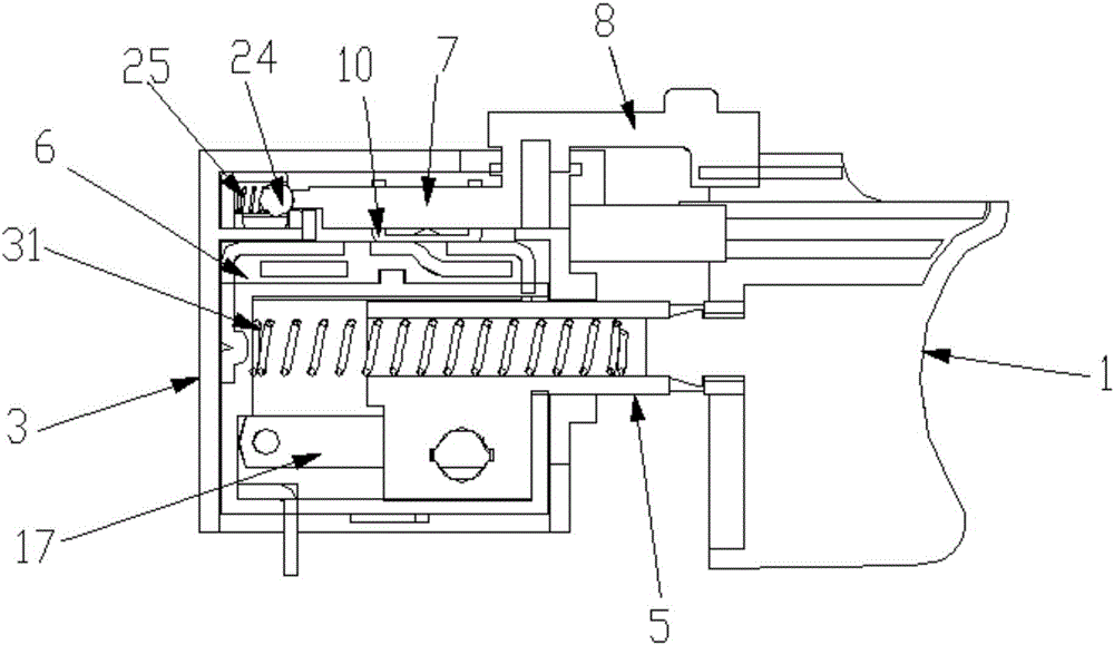
[0034] Such as Figure 1-9 As shown, the reversing switch of the electric tool includes a button 1, a base 3, an inner base 4 located below the base 3, a push rod 5 arranged in the inner base 4 connected to the button 1, and the inner base 4, the reversing base 6 above the base 3, the reversing handle 7 arranged inside the base 3 and above the reversing base 6, the shifting rod 8 arranged outside the base 3, connecting the reversing shifting handle 7 and the shifting rod 8, the first reversing movable contact piece 10 and the second reversing movable contact piece 11 clamped on the reversing toggle handle 7, it is characterized in that, the reversing base 6 is provided with an end extension The first terminal 12 and the second terminal 13 of the base 3, the other end of the first terminal 12 and the other two ends of the second terminal 13 are in the reversing base 6, and the first terminal 12 The other end is located in the middle of the other two ends of the second terminal...


PUM


Abstract

The invention discloses a reversing switch of an electric tool. The reversing switch comprises a button, a base, an inner base, a push rod, a reversing base and a reversing shift handle, wherein the push rod is connected with the button; the reversing base is arranged above the inner base; the reversing handle is arranged above the reversing base; a first terminal of which one end extends out of the base and a second terminal of which one end extends out of the base are arranged in the reversing base; one end part of the first terminal is positioned between two end parts of the second terminal; the first terminal, the second terminal and the reversing base are integrated; one end part of a third terminal and one end part of a fourth terminal are arranged on the base respectively; the other end part of the third terminal and the other end part of the fourth terminal pass through a positioning groove and extend onto the reversing base; the end parts extending onto the reversing base are on the same plane as end parts of the first terminal and the second terminal in the reversing base; a V-shaped movable contact spring is hinged to the fourth terminal; a power supply terminal corresponding to the V-shaped movable contact spring is arranged in the base; a positioning plate is arranged above the reversing base; and a limiting device which is connected with the reversing shift handle is arranged above the positioning plate. The switch is easy to assemble, low in cost and accurate in reversing, has high reliability, and can be switched on automatically.

Description

technical field [0001] The invention relates to an electric tool switch, in particular to an electric tool switch with a reversing device. Background technique [0002] The reversing switch of commonly used electric tools includes a button, a base, a push rod set in the base and connected to the button, a reversing handle set inside the base, a lever set outside the base, and a connection reversing The connecting shaft of the shifting handle and the shifting rod, the reversing terminal group arranged in the base, the first reversing moving contact and the second reversing moving contact that are clamped on the reversing handle and contact with the reversing base The reversing switch with this structure is difficult to assemble, has a high defect rate and high cost, and poor contact is prone to occur during reversing operation, resulting in low reliability of the switch. Contents of the invention [0003] The problem to be solved by the present invention is to provide an e...

Claims


Application Information

Patent Timeline
Patent Type & Authority Applications(China)
IPC IPC(8): H01H9/06
CPCH01H9/063
Inventor 贺培
Owner ZHANGJIAGANG HUAJIE ELECTRONICS
Why Eureka
Try Eureka