
A permanent magnet motor rotor and generator

A permanent magnet motor and rotor technology, which is applied in the direction of magnetic circuit rotating parts, magnetic circuit shape/style/structure, etc., can solve the problems of complicated rotor assembly and easy demagnetization, and achieves easy promotion, simple installation process and good use effect. Effect

Active Publication Date: 2019-02-01
北京三一智能电机有限公司
View PDF5 Cites 0 Cited by
  • Summary
  • Abstract
  • Description
  • Claims
  • Application Information

AI Technical Summary

Problems solved by technology

[0005] When the rotor is working, due to the high temperature of the magnetic steel, it is easy to demagnetize;
[0006] The overall assembly of the rotor is complex

Method used


Image

  • A permanent magnet motor rotor and generator
  • A permanent magnet motor rotor and generator
  • A permanent magnet motor rotor and generator

Examples


Embodiment 1

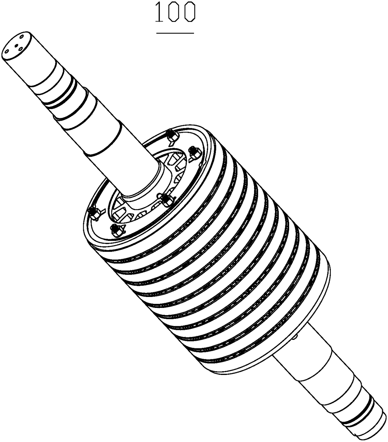
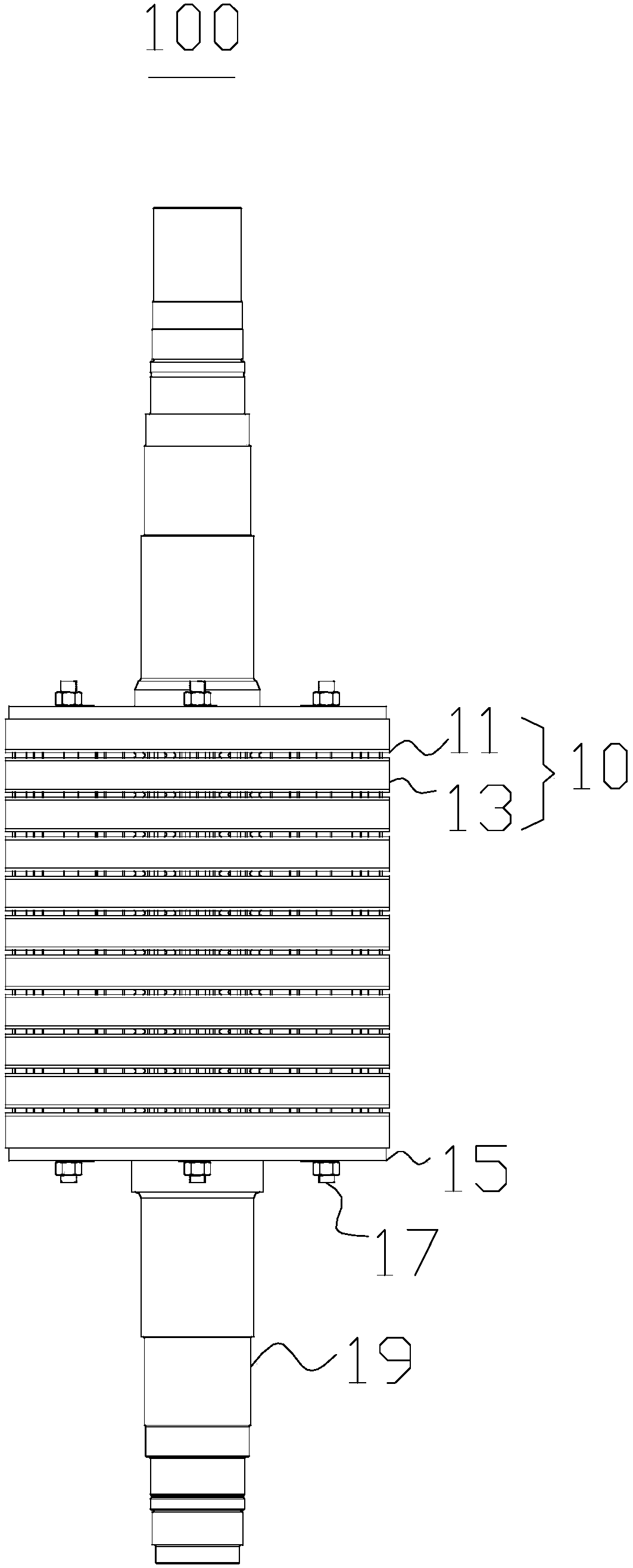
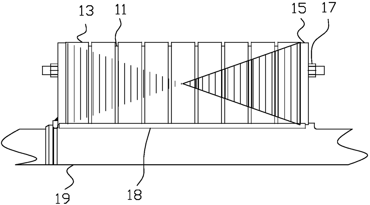
[0046] Please refer to figure 1 with figure 2 , this embodiment provides a permanent magnet motor rotor 100, including a rotor core 10, a pressure plate 15 and tension bolts 17, the rotor core 10 is formed by stacking a plurality of rotor punches 13 and a plurality of ventilation slot plates 11.

[0047] Two adjacent rotor punches 13 are separated by a ventilation slot plate 11, the ventilation slot plate 11 includes at least two ventilation slots and a plurality of spacer bars, the spacer bars are located between the two ventilation slots and surround the rotor core. The axis of 10 is distributed in a ring, the length direction of the spacer is arranged along the radial direction of the rotor core 10 and a plurality of radial ventilation passages are formed between two adjacent ventilation slots, and the pressure plates 15 are located at both ends of the rotor core 10 and Tighten by tensioning bolt 17.

[0048] Specifically, the rotor punch 13 is formed by stacking a plura...

Embodiment 2

[0084]This embodiment also provides a generator, which includes the permanent magnet motor rotor 100 mentioned above, the structure of the permanent magnet motor rotor 100 can refer to embodiment 1, the generator has all the functions of the permanent magnet motor rotor 100 .

[0085] When the generator with the permanent magnet motor rotor 100 is in working state, the magnet steel 137 has a better heat dissipation effect, and the magnet steel 137 is not easy to demagnetize.

[0086] To sum up, the present invention provides a permanent magnet motor rotor 100. By setting radial ventilation passages, the air in the rotor core 10 can achieve a better flow, and the flowing air takes away the heat on the magnetic steel 137. The exchange with the external air reduces the temperature of the magnetic steel 137, ensuring that the magnetic steel 137 will not be demagnetized due to overheating even if it works for a long time. Through the cooperation of the ventilation slot plate 11 an...


PUM


Abstract

The invention provides a permanent magnet motor rotor and generator, and belongs to the technical field of motors. The permanent magnet motor rotor includes a rotor core, pressing plates and tension bolts. The rotor core is formed by lamination of a plurality of rotor punching sheets and a plurality of ventilating slot plates, and two adjacent rotor punching sheets are separated by a ventilating slot plate. Each ventilating slot plate includes at least two ventilating slot sheets and a plurality of spacing bars, a plurality of radial ventilation channels are formed between two adjacent ventilating slot sheets, and the pressing plates are located at two ends of the rotor core and are tensioned through the tension bolts. The generator has all the functions of a permanent magnet motor. The radial ventilation channels enable air in the rotor core to realize relatively good flow, flowing air takes away heat on magnetic steel and exchanges with outside air, the temperature of the magnetic steel is reduced, and an effect that the magnetic steel is not demagnetized due to overheating even if the magnetic steel works for a long time is guaranteed. Through cooperation of the ventilating slot plates and the rotor punching sheets, the whole mounting process is simple, a using effect is relatively good, and popularization is facilitated.

Description

technical field [0001] The invention relates to the technical field of motors, in particular to a permanent magnet motor rotor and a generator. Background technique [0002] Generators are usually composed of stators, permanent magnet motor rotors, end covers, bearings and other components. The stator consists of the stator core, frame and other structural parts that fix these parts. The permanent magnet motor rotor is composed of permanent magnet motor rotor core (or magnetic pole, magnetic yoke) winding, guard ring, center ring, slip ring, fan and rotating shaft and other components. The stator of the generator and the rotor of the permanent magnet motor are connected and assembled by the bearing and the end cover, so that the rotor of the permanent magnet motor can rotate in the stator and do the movement of cutting the magnetic force line, thereby generating an induced potential, which is drawn out through the terminal and connected to the circuit , a current is genera...

Claims


Application Information

Patent Timeline
Patent Type & Authority Patents(China)
IPC IPC(8): H02K1/32H02K1/27
CPCH02K1/27H02K1/32
Inventor 马贤好王民伟李书杰王华军罗娟
Owner 北京三一智能电机有限公司
Learn More