One-body motor integrating brake

A brake and integrated technology, which is applied in the direction of controlling mechanical energy, electromechanical devices, electrical components, etc., can solve the problem of low precision of the output shaft, achieve the effect of convenient maintenance, and reduce design and installation errors

Active Publication Date: 2017-02-15
CHINA ELECTRONIC TECH ROBOT CO LTD
View PDF8 Cites 13 Cited by
  • Summary
  • Abstract
  • Description
  • Claims
  • Application Information

AI Technical Summary

Problems solved by technology

[0005] The purpose of the present invention is to provide an integrated motor with an integrated brake to solve the problems in the prior art that the accuracy of the output shaft is gradually lowered due to the separate installation of the motor and the reducer or the motor and the brake.

Method used


Image

  • One-body motor integrating brake
  • One-body motor integrating brake
  • One-body motor integrating brake

Examples


Embodiment Construction

[0023] The present invention will be described in further detail below in conjunction with the accompanying drawings and specific embodiments.

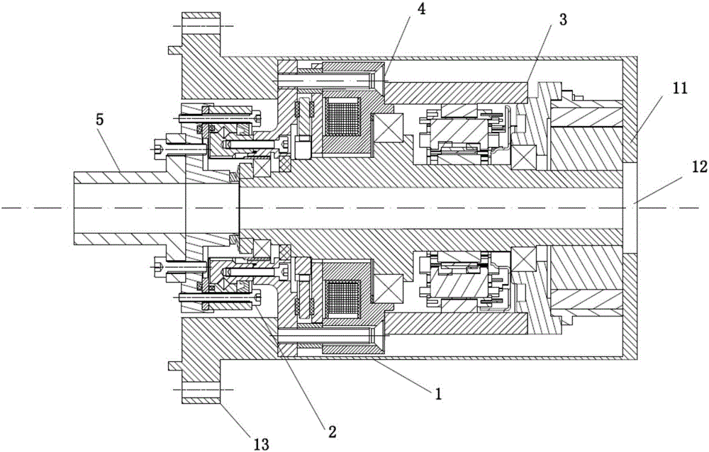
[0024] Such as figure 1 As shown, the embodiment of the present invention includes a casing 1 , a harmonic reducer 2 , a servo motor 3 , a brake 4 and an output shaft 5 . The casing 1 is in the shape of a barrel, with one end open and one end closed by an end plate 11 , but a through hole 12 is provided in the central area of ​​the end plate 11 . From the opening of the casing 1, a harmonic reducer 2, a brake 4, and a servo motor 3 are sequentially arranged therein. The output shaft 5 is arranged on the harmonic reducer 2 .

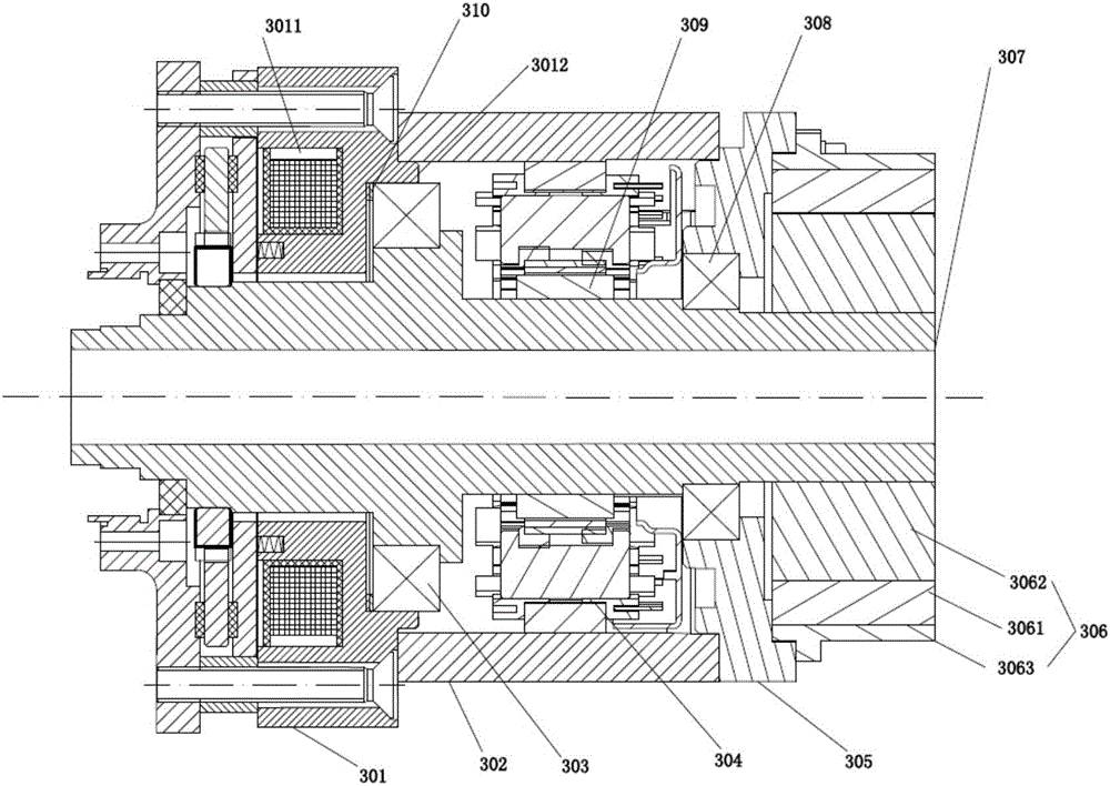
[0025] Specifically, as figure 1 , figure 2 As shown, the servo motor 3 includes: a front end cover 301, a rear end cover 305, a front bearing 303, a rear bearing 308, a stator (or a servo motor stator) 304, a magnetic steel 309, a rotating shaft 307, a motor housing 302 and a resolver 306 , Block 310 and s...


PUM


Abstract

The present invention provides an one-body motor integrating a brake. The motor comprises a casing; a servo motor including a motor casing, a front end cover, a rear end cover, a spindle which is located in the motor casing, wherein the front end cover is cyclic annular, and the front side of the front end cover is provided with a front annular groove and a plurality of blind holes, and the partial cross section of the front end of the spindle is elliptical; a brake consisting of a coil, a movable iron core, a friction plate, a brake disc, a fixing plate, an external gear and a plurality of brake springs, wherein the coil is embedded in the first annular groove, the movable iron core is located at the outer sides of the front end cover and the coil, one end of each brake spring inserts one blind hole, the other one end of each brake spring is sleeved and fixed at the front end of the spindle, the brake disc is located at the outer side of the movable iron core and is provided with inner teeth engaged with the external gear, the fixing plate is located at the outer side of the brake disc, and the friction plate is arranged between the movable iron core and the brake disc and between the fixing plate and the brake disc; and an output shaft. The one-body motor integrating a brake at least integrates the servo motor and the brake so as to reduce the design and installation error caused by the split-type structure.

Description

technical field [0001] The invention relates to the technical field of servo motor and brake assembly, in particular to an integrated motor with integrated brake. Background technique [0002] As motors, especially servo motors, are widely used in the industrial field, the requirements for the accuracy and torque of motor output are also getting higher and higher. At present, the motors on the market are generally connected to the load after passing through the reducer or brake, that is, the motor, reducer and brake are basically installed and fixed separately. Such an installation structure will introduce many error factors and reduce the final output shaft. accuracy. [0003] In addition, the overall volume of the motor, reducer, or brake of the aforementioned structure is very large, and the appearance structure is not beautiful. During installation, the motor, reducer, or brake need to be installed on the base separately, which is cumbersome to assemble and difficult to...

Claims


Application Information

Patent Timeline
Patent Type & Authority Applications(China)
IPC IPC(8): H02K7/102
CPCH02K7/1023
Inventor 王卫军李亚运刘立冬徐友法苏陈罗金龙王军
Owner CHINA ELECTRONIC TECH ROBOT CO LTD
Why Eureka
Try Eureka