Multi-azimuth mobile scanner
A mobile scanner technology, applied in the scanning field, can solve the problems of inconvenient use, poor versatility, and inability to complete scanning, etc., and achieve the effect of reasonable structural design, strong versatility, and smooth movement
- Summary
- Abstract
- Description
- Claims
- Application Information
AI Technical Summary
Problems solved by technology
Method used
Image
Examples
Embodiment 1
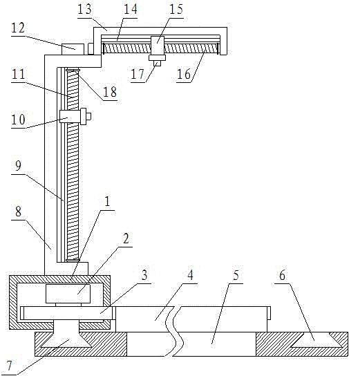
[0016] Such as figure 1 and figure 2 As shown, a multi-directional movable scanner includes a base 1, a driving device A2 is arranged in the base 1, a gear 3 is connected to the output shaft of the driving device A2, and the gear 3 The gear teeth on the right side extend out of the base 1, the gear 3 meshes with the ring gear 4 on the right side, the ring gear 4 is fixed on the upper surface of the support platform 5, and the upper surface of the support platform 5 The outer side of the upper ring gear 4 is provided with an annular chute 6, and a sliding block 7 matched with it is arranged in the chute 6, and the sliding block 7 is fixedly connected on the lower surface of the gear 3. The upper surface of the base 1 is provided with a vertical support frame 8, the upper surface of the vertical support frame 8 is fixed with a horizontal support frame 13, and the vertical support frame 8 and the horizontal support frame 13 are respectively provided with vertical guide rods 9 ...
Embodiment 2
[0019] Such as figure 1 and figure 2 As shown, a multi-directional movable scanner includes a base 1, a driving device A2 is arranged in the base 1, a gear 3 is connected to the output shaft of the driving device A2, and the gear 3 The gear teeth on the right side extend out of the base 1, the gear 3 meshes with the ring gear 4 on the right side, the ring gear 4 is fixed on the upper surface of the support platform 5, and the upper surface of the support platform 5 The outer side of the upper ring gear 4 is provided with an annular chute 6, and a sliding block 7 matched with it is arranged in the chute 6, and the sliding block 7 is fixedly connected on the lower surface of the gear 3. The upper surface of the base 1 is provided with a vertical support frame 8, the upper surface of the vertical support frame 8 is fixed with a horizontal support frame 13, and the vertical support frame 8 and the horizontal support frame 13 are respectively provided with vertical guide rods 9 ...
PUM
 Abstract
Description
Claims
Application Information
 - R&D
- Intellectual Property
- Life Sciences
- Materials
- Tech Scout
- Unparalleled Data Quality
- Higher Quality Content
- 60% Fewer Hallucinations
Browse by: Latest US Patents, China's latest patents, Technical Efficacy Thesaurus, Application Domain, Technology Topic, Popular Technical Reports.
© 2025 PatSnap. All rights reserved.Legal|Privacy policy|Modern Slavery Act Transparency Statement|Sitemap|About US| Contact US: help@patsnap.com


