High Frequency Surgical Cutting Ring for Flexible Endoscopy

一种切环、近端的技术,应用在内窥镜、手术、加热外科器械等方向,达到应用简单的效果

Active Publication Date: 2020-09-01
ENDOX PRECISION INSTR TECH CO LTD +1
View PDF10 Cites 0 Cited by
  • Summary
  • Abstract
  • Description
  • Claims
  • Application Information

AI Technical Summary

Problems solved by technology

[0010] Another problem when applying all polypectomy rings that have been used so far is that neither the endoscopist nor his assistant (such as an endoscopy nurse) can observe or Control: Whether the HF surgical incision loop is closed, and if so, how quickly

Method used


Image

  • High Frequency Surgical Cutting Ring for Flexible Endoscopy
  • High Frequency Surgical Cutting Ring for Flexible Endoscopy
  • High Frequency Surgical Cutting Ring for Flexible Endoscopy

Examples


Embodiment Construction

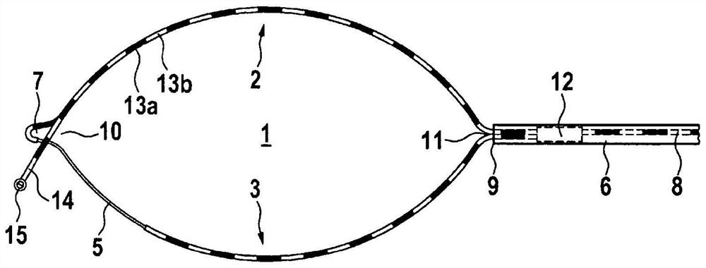
[0034] exist figure 1 A high-frequency surgical cutting ring 1 for flexible endoscopy according to the present invention is shown in . The cutting ring includes a first ring part 2 and a second ring part 3 . The ring parts themselves preferably consist of spring-elastic, metallic round and / or flat wires. Alternatively, the ring part may also comprise metallic litz wires. These ring parts have a proximal end 11 and a distal end 10 respectively. The proximal ends of the ring portions together form the proximal end 11 of the ring. The ring part is mechanically and electrically conductively connected to at least one steering wire 8 , for example by means of a connecting element 12 , or is designed as a steering wire. For example, at least one of the ring parts can be substantially extended on the proximal side, so that the extension acts as a steering wire. Furthermore, the two ring parts form the ring distal end 10 with the ring tip 7 . A ring tip is optional, but often req...


PUM


Abstract

The present invention relates to a polypectomy ring comprising two ring portions, the polypectomy ring having one ring portion which is completely electrically insulated and the other ring portion which is not electrically insulated in at least one distal section. Furthermore, the ring has at least one electrically insulating, high-frequency surgically inactive sled on its distal end.

Description

technical field [0001] The invention relates to an instrument or a high-frequency surgical cutting ring as part of an instrument for the endoscopically controlled removal of polypoid or flattened growths of diseased mucosal regions (so-called lesions) of the gastrointestinal tract. Also, these instruments are called polypectomy devices or (by part for whole) polypectomy rings. Background technique [0002] One of the first such devices was described in German Utility Model Patent No. 71115781 in 1971. Today, as then, these instruments basically consist of a flexible catheter about 2 m long made of plastic, a metallic steering wire movable in the catheter, a high-frequency surgical The surgical metal cutting ring and the operating handle at the other end (the so-called proximal end) of the manipulation wire and catheter. For more than forty years, catheters and cutting rings of these instruments have been used through the so-called instrument channel or working channel of f...

Claims


Application Information

Patent Timeline
Patent Type & Authority Patents(China)
IPC IPC(8): A61B18/12A61B18/14
CPCA61B18/12A61B18/1482A61B18/1492A61B2018/00982A61B2018/1475A61B2018/1497A61B2018/1465A61B2018/141A61B2018/00601A61B2018/00494A61B2018/00077A61B2018/00083
Inventor 君特·费林
Owner ENDOX PRECISION INSTR TECH CO LTD
Why Eureka
Try Eureka