Method for testing brake systems of motor vehicles

A technology for braking systems and motor vehicles, applied in the direction of braking safety systems, etc., can solve problems such as wrong evaluation and wrong judgment, and achieve the effect of improving the accuracy rate

Inactive Publication Date: 2017-02-15
DURR SOMAC
View PDF7 Cites 0 Cited by
  • Summary
  • Abstract
  • Description
  • Claims
  • Application Information

AI Technical Summary

Problems solved by technology

[0008] Therefore, the current common method of assessing the remaining air ratio will inevitably lead to a large number of misjudgments, which will not only lead to wrong assessments as "abnormal" (hereinafter referred to as "NIO"), but also cause wrong assessments as "normal" (hereinafter referred to as "IO")

Method used


Image

  • Method for testing brake systems of motor vehicles

Examples


Embodiment Construction
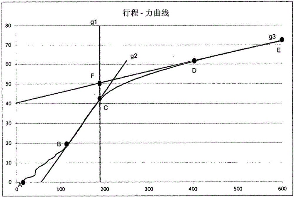
[0017] In the area of ​​the curve between points A and B, only parts of the pedal mechanism including the brake booster move, but without a reinforcing effect.

[0018] In the curve region between points B and C, the brake master cylinder begins to move. Here, the brake linings are not yet in contact so that no appreciable hydraulic pressure can develop. The movement is approximately linear. However, movement of the seal can be seen in this region. As long as enough measuring points are found in this linear relationship, the area can be described by the straight line "g2". The reference of this measuring point is a determined correlation.

[0019] In a further extension, the travel-force curve transitions into a curved region. The fixed point C is determined by the start of a pronounced bending of the travel-force curve in the direction of the point D. FIG. Point C is where the hydraulic pressure rises significantly on the curve. The straight line "g1" extending vertical...


PUM


Abstract

The invention relates to a method for testing brake systems of motor vehicles during the manufacturing process, in the assembly line of automobile manufacturers, in which method the brake pedal is actuated by means of an automatically controlled device and the pedal travel and pedal force are measured by means of associated measuring devices. The invention addresses the problem of modifying a brake pedal test which is known per se in such a way that the proportion of false NIO evaluation results regarding the residual air can be substantially reduced, and the proportion of false IO evaluation results can be reduced at least to an insignificant proportion. This problem is solved in that a travel-force curve is plotted on the basis of pedal travel and pedal force during pedal motion, and is evaluated by means of a physical brake system model which isolates the constructive influence of the individual components of the brake system. In addition, the travel difference between different fixed points of different vehicles is taken into account when calculating the pedal travel in order to compensate for the variable influence of wheel brake slack on pedal travel.

Description

technical field [0001] The invention relates to a method for checking the braking system of a motor vehicle during the manufacturing process on an assembly line of a motor vehicle manufacturer, wherein the brake pedal is actuated by an automatically controlled device and wherein the pedal travel and the pedal are measured by corresponding device technology force. Background technique [0002] The brake system of a motor vehicle is a safety-relevant component and usually has to be inspected both during the production process at the vehicle manufacturer and during subsequent vehicle repairs. In this case, the brake system is tested during production, in particular after filling with fuel. The purpose of this test is to detect possible cracks or air inclusions in the system. At the same time, a defined position of the elevator and the flexibility of the movable parts in the braking system should be ensured. For this detection, different types of technical solutions are known...

Claims


Application Information

Patent Timeline
Patent Type & Authority Applications(China)
IPC IPC(8): B60T17/22
Inventor 米夏埃尔·奥特雷赫尔米夏埃尔·舒尔特海斯
Owner DURR SOMAC
Why Eureka
Try Eureka