Optical components and surface light source devices

An optical element, surface light source technology, applied in optical elements, plane light source, optics, etc., can solve the problem of too dark around

Active Publication Date: 2019-05-03
ORMON CORP
View PDF8 Cites 0 Cited by
  • Summary
  • Abstract
  • Description
  • Claims
  • Application Information

AI Technical Summary

Problems solved by technology

[0005] However, with regard to the luminance distribution of the surface light source device of the direct light source system, if there is no optical element such as a microlens array, as in Figure 11 As shown by the dotted line in (a), the top of the light source is too bright, and the surrounding area is too dark

Method used


Image

  • Optical components and surface light source devices
  • Optical components and surface light source devices
  • Optical components and surface light source devices

Examples


Embodiment Construction

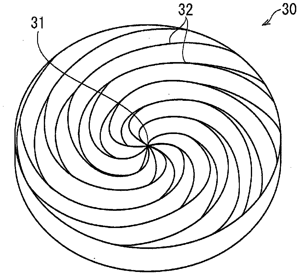
[0047] Below, according to Figure 1 to Figure 9 One embodiment of the present invention will be described.

[0048] An application example of applying the optical element and the surface light source device of this embodiment to an illuminated push button switch is described, wherein the illuminated push button switch is used, for example, as a switch installed on a wall surface of an elevator hall The indicator switch for the up or down direction set in the operation panel of the elevator on the elevator; or the indicator switch installed in the elevator to indicate door opening, door closing and floor number, etc. Moreover, the optical element and the surface light source device of the present invention are not limited to the application of the illuminated pushbutton switch, and can also be applied to other fields.

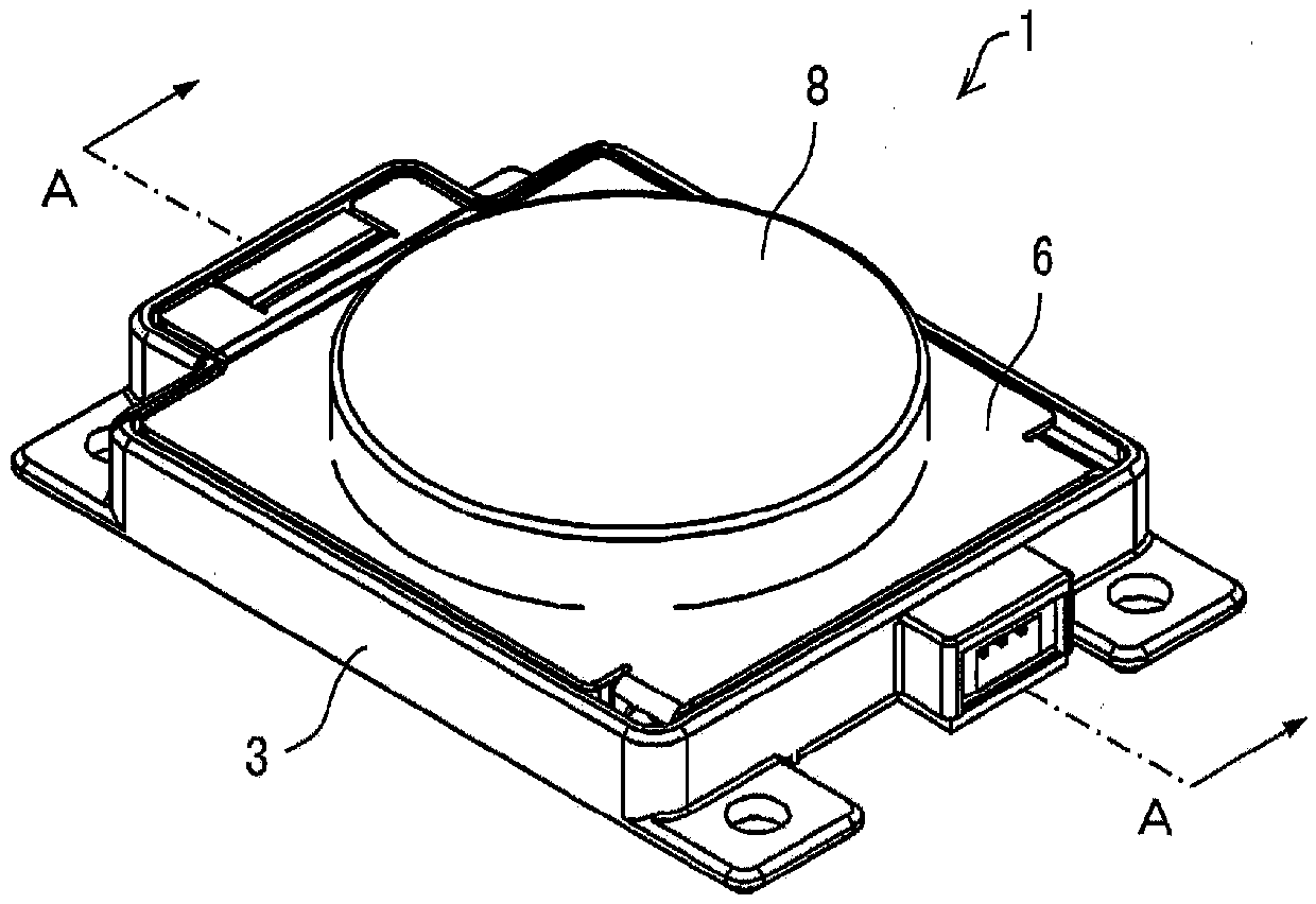
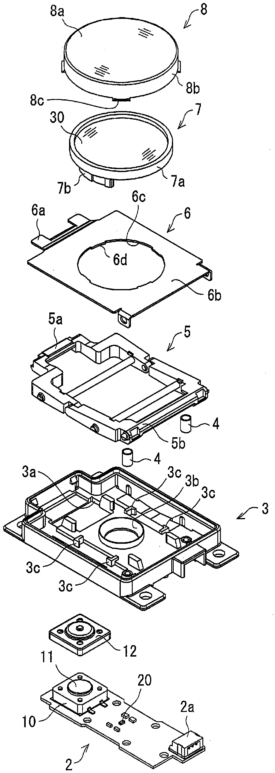
[0049] according to Figure 2 ~ Figure 4 , the configuration of the illuminated push button switch 1 including the optical element and the surface light sour...


PUM


Abstract

Provided are an optical element and a planar light source device capable of achieving, in a directly-below light source scheme, a uniform planar light emission while the distance in the emission direction is kept small. The optical element (30) comprises over a flat plate surface at least one prism group formed by a plurality of prism top portions (32), each extending in the shape of a spiral from a central axis (31) to the outer periphery.

Description

technical field [0001] The present invention relates to an optical element and a surface light source device provided with a prism group on the front. Background technique [0002] For example, an illuminated pushbutton switch is provided in an elevator so as to enable input of a destination floor. In recent years, it is desired that the illuminated pushbutton switch emits light evenly. [0003] As a structure for uniformly lighting the conventional illuminated push button switch, such as Figure 10 As shown in (a), (b), and (c), three control methods are generally known. Among them, in Figure 10 As shown in (a), the method of disposing the convex lens 102 directly above the light source 101 to control the directivity, or Figure 10 In the so-called direct light source method such as the light guide control method in which the light from the light source 111 is emitted through the light guide pipe 112 shown in (b), there is a problem that the distance in the emission direct...

Claims


Application Information

Patent Timeline
Patent Type & Authority Patents(China)
IPC IPC(8): F21K9/69F21V5/00F21V5/02F21V5/04F21V17/00G02B3/08G02B5/04H01L33/58F21Y115/10F21Y105/00
CPCF21S2/00F21V5/04F21V17/00G02B3/08G02B5/04H01L33/58
Inventor 奥田满篠原正幸田上靖宏
Owner ORMON CORP
Why Eureka
Try Eureka