
Drive circuit for a led

A LED drive and drive circuit technology, applied in the field of LED control, can solve the problems of phosphor change, secondary optical device temperature management, light flicker, etc.

Active Publication Date: 2012-05-09
TRIDONIC
View PDF6 Cites 0 Cited by
  • Summary
  • Abstract
  • Description
  • Claims
  • Application Information

AI Technical Summary

Problems solved by technology

[0004] However, current LED lighting systems often have the disadvantage that color or brightness may change due to aging or due to replacement of individual LEDs or LED assemblies
Additionally, secondary optics have an impact on temperature management by blocking thermal radiation
In addition, due to aging and heat, the phosphor of the LED may change
[0005] Brightness changes are usually only possible with complex control circuits and cannot be simply interfaced with common dimmers due to the flickering of light that occurs when working with most dimmers, and even these dimmers cannot normal work

Method used


Image

  • Drive circuit for a led
  • Drive circuit for a led
  • Drive circuit for a led

Examples


Embodiment Construction

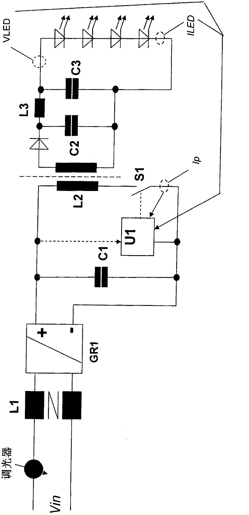
[0022] Combine the following figure 1 The embodiment with LED driving circuit is used to illustrate the basic circuit for driving LEDs, which is the basis of the present invention.

[0023] The LED driving circuit has a power supply interface, a filter circuit (L1), a rectifier (GR1), an inductor (L2) and a switch (S1). The rectifier (GR1) is followed by a snubber element (C1) which preferably only serves to filter out high-frequency voltage variations without exerting a significant smoothing effect on the voltage at the output of the rectifier (GR1). The snubber element ( C1 ) is for example a capacitor, preferably a smoothing capacitor. The inductor (L2) preferably has a primary coil (L2p) and a secondary coil (L2s) coupled to the primary coil.

[0024] When the switch is on, the inductor (L2) is magnetized; and when the switch S1 is off, the inductor (L2) is demagnetized, and at least during the demagnetization phase, current is delivered to the LED through the inductor (...


PUM


Abstract

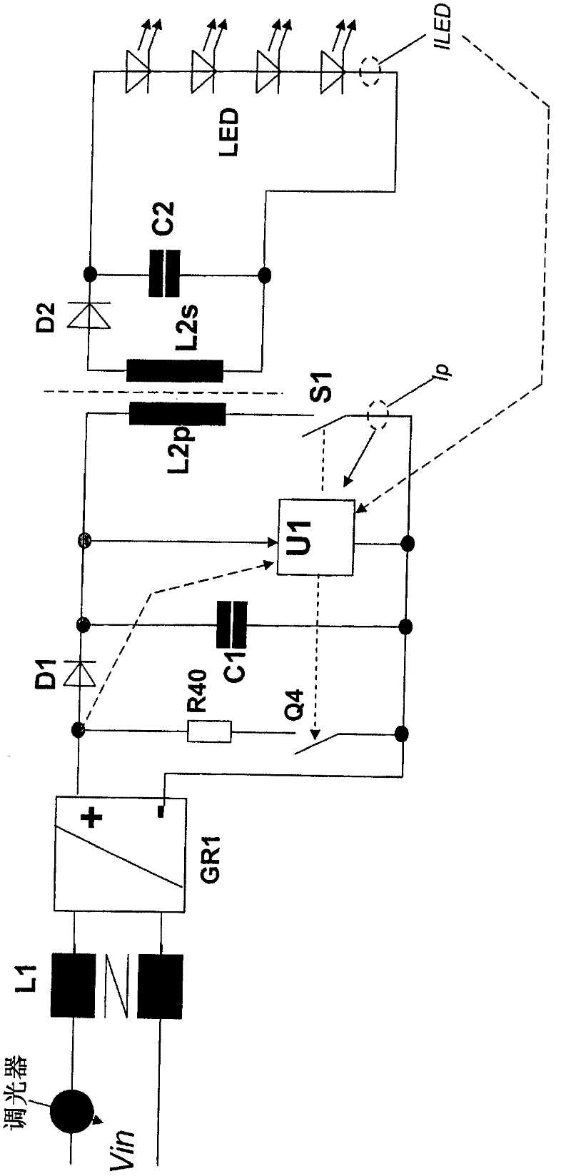
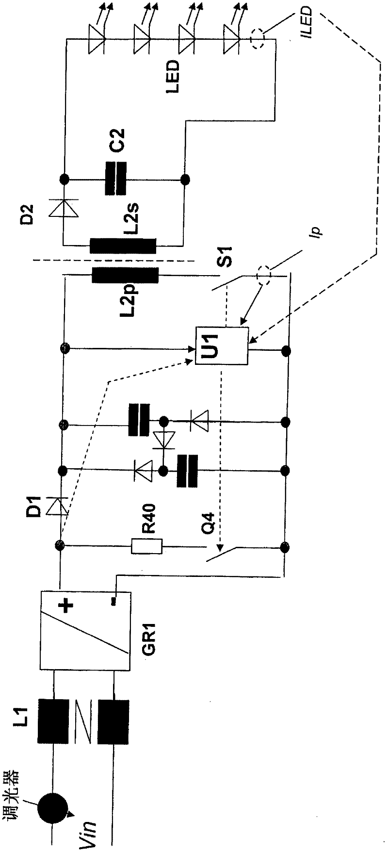
The invention relates to a drive circuit for an LED, comprising a connection for a supply voltage, a rectifier and a filter circuit, a buffer element, an inductor, and a switch, wherein the inductor becomes magnetized when the switch is closed, and the inductor becomes demagnetized when the switch is open, and, at least during the phase of demagnetization, the current feeds the LED through said inductor, wherein a current detector is contained between the rectifier and the buffer element, wherein at the output of the rectifier a bypass circuit is present, which is deactivated when the current detector allows the current to flow.

Description

technical field [0001] The invention relates to an LED driver circuit according to the preamble of claim 1 and also to a method of controlling an LED according to the preamble of claim 19 . Background technique [0002] This driving circuit is used in lighting systems to realize colored or regional lighting for rooms, roads or escape routes. Typically, lighting devices are driven by driver devices and activated when required. For this lighting, organic or inorganic light emitting diodes (LEDs) can be used as light sources. [0003] For lighting, light-emitting diodes are increasingly used as light sources instead of gas-discharge lamps and incandescent lamps. The efficiency and the amount of light emitted by a light emitting diode continue to rapidly increase, so that it has been used in various fields of daily lighting. Light-emitting diodes, however, are point sources of light and emit strongly concentrated light. [0004] However, current LED lighting systems often ha...

Claims


Application Information

Patent Timeline
IPC IPC(8): H05B33/08H05B44/00
CPCH05B33/0815H05B45/3725H05B45/382
Inventor 迈克尔·齐默尔曼爱德华多·佩雷拉
Owner TRIDONIC
Learn More