Particle bed filtering and dust removing device

A particle bed filtration and particle bed filter technology, applied in the directions of dispersed particle filtration, combined device, transportation and packaging, can solve the problems of increasing filtration load, affecting dust settlement and discharge, blade wear, etc., to achieve continuous high-efficiency filtration, improve The effect of filtration efficiency

Active Publication Date: 2017-02-22
NINGBO UNIV
View PDF7 Cites 2 Cited by
  • Summary
  • Abstract
  • Description
  • Claims
  • Application Information

AI Technical Summary

Problems solved by technology

However, in such an arrangement, since the blowback air volume of the particle layer in the inner casing is 1.5 to 2.5 times the filtered air flow rate of the particle layer in the inner casing, it will cause the lowest inner layer of the second layer. The blowback gas of the particle layer in the shell cannot be accepted by the particle layer in the inner casing of the lowest first layer, which will cause the backflush gas to carry the dust and flow upwards, while the particle bed filters the inner layer of the lowest first layer in the dust collector. The blowback air of the particle layer in the shell can only flow upwards, causing the dust to swirl between the lowest first layer and the lowest third layer, affecting the dust settlement and discharge
In order to make the blowback gas flow downward, although it is possible to use air suction at the lower part of the particle bed filter dust collector to force the blowback gas and dust to be drawn from the lower part and circulate back to the dusty gas inlet of the particle bed filter dust collector, this will not only Dust is repeatedly filtered, the filter load is increased, and the blades in the circulating fan are severely worn, especially when the temperature is high and the dust hardness is high, the blades in the circulating fan are more severely worn, and when the gas contains a lot of tar vapor , the anti-tarring in the circulating fan is also a big problem to be solved

Method used


Image

  • Particle bed filtering and dust removing device
  • Particle bed filtering and dust removing device
  • Particle bed filtering and dust removing device

Examples


Embodiment 1

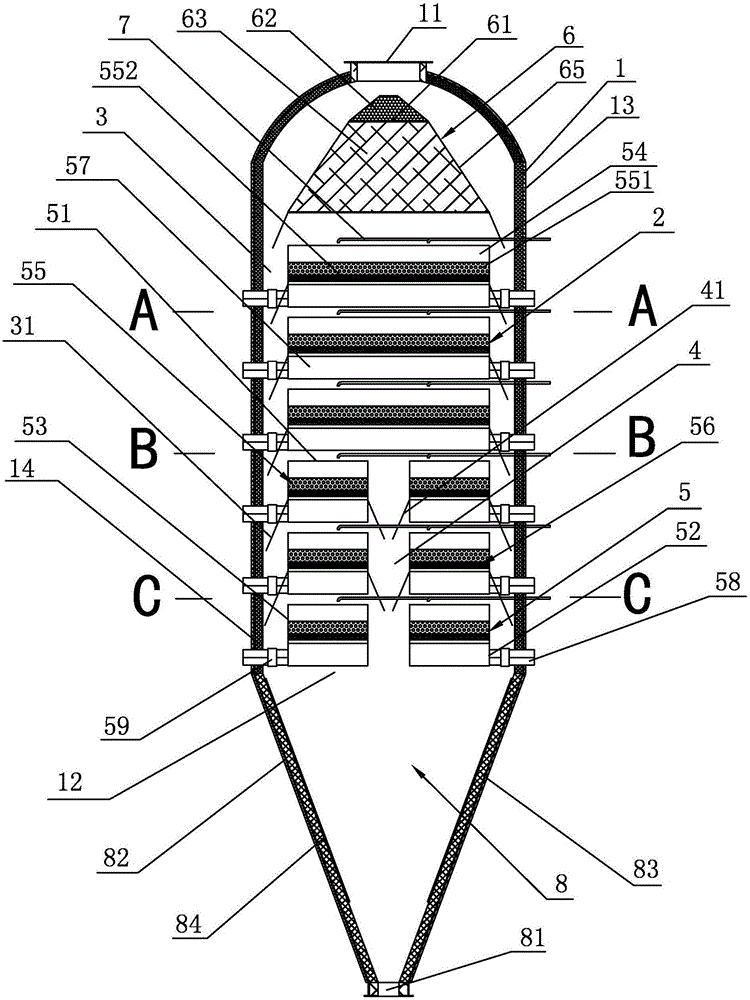
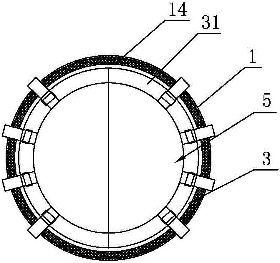
[0026] A kind of particle bed filter dust removal device that present embodiment proposes, such as Figure 1a to Figure 1d As shown, it includes an outer casing 1 with a circular cross-section. The top of the outer casing 1 is provided with a dusty gas inlet 11 communicating with the upstream air intake pipe (not shown in the figure), and the bottom of the outer casing 1 is provided with a dust exhaust. Outlet 12, the interior of the outer shell 1 is centered in the vertical direction with six layers of granular bed filters 2 that have gaps with the inner wall of the outer shell 1, and the gaps between the inner wall of the outer shell 1 and the outer peripheries of all granular bed filters 2 As the airflow chamber 3, so that the airflow chamber 3 is located at the periphery of the particle bed filter 2, such an arrangement makes there be a large enough space between the periphery of the particle bed filter 2 and the inner wall of the outer shell 1, which is convenient for pers...

Embodiment 2

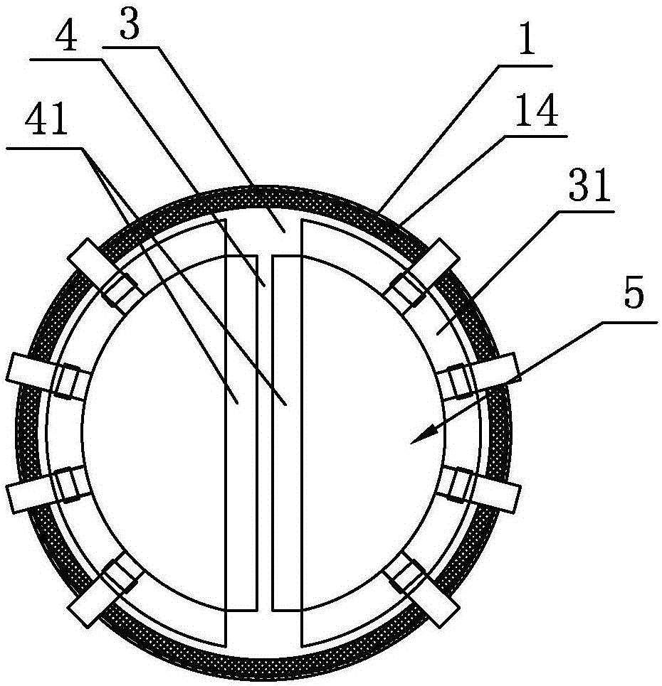
[0035] A kind of particle bed filter dust removal device that present embodiment proposes, such as figure 2 As shown, its structure is not much different from that of the particle bed filter and dust removal device of Embodiment 1, the difference is only that: the back blowing gas settling chamber 4 in the particle bed filter and dust removal device of the present embodiment only runs through two layers of particle beds The filter 2 is only the particle bed filter 2 of the lowest layer and the particle bed filter 2 of the second lowest layer. That is, the particle bed filter and dust removal device of this embodiment includes an outer casing 1 with a circular cross section, the top of the outer casing 1 is provided with a dust-containing gas inlet 11 communicating with the upstream air intake pipe, and the bottom of the outer casing 1 is provided with a dust outlet. 12. The interior of the outer shell 1 is vertically centered with six layers of granular bed filters 2 that hav...

Embodiment 3

[0038] A kind of particle bed filter dust removal device that present embodiment proposes, such as Figure 3a with Figure 3b As shown, its structure is not much different from the structure of the particle bed filter and dust removal device of Embodiment 1, the difference is only that: the back blowing gas settling chamber 4 in the particle bed filter and dust removal device of the present embodiment runs through all the particle bed filters 2. That is, the particle bed filter and dust removal device of this embodiment includes an outer casing 1 with a circular cross section, the top of the outer casing 1 is provided with a dust-containing gas inlet 11 communicating with the upstream air intake pipe, and the bottom of the outer casing 1 is provided with a dust outlet. 12. The interior of the outer shell 1 is vertically centered with six layers of granular bed filters 2 that have gaps with the inner wall of the outer shell 1, and the gaps between the inner wall of the outer s...


PUM


Abstract

The invention discloses a particle bed filtering and dust removing device. The device comprises a casing, wherein a dust-containing air inlet is arranged at the top of the casing, a dust outlet is arranged at the bottom of the casing, at least two layers of particle bed filters are vertically arranged in the casing, a back blowing air settling chamber is formed inside, a gap between the inner wall of the casing and the peripheries of the particle bed filters serves as an airflow chamber, the back blowing air settling chamber penetrates through at least two layers of particle bed filters from the lowest layer, the back blowing air settling chamber communicates with the dust outlet, each particle bed filter which is not penetrated by the back blowing air settling chamber comprises at least one filter unit, each particle bed filter which is penetrated by the back blowing air settling chamber comprises at least two filter units distributed on two sides of the back blowing air settling chamber, the airflow chamber and the back blowing air settling chamber communicate with a dust-containing air vent port, and a first inertia separation air deflector forming an angle of 10-45 degrees with the vertical direction is arranged at the dust-containing air vent port in the back blowing air settling chamber. The device has the advantages that back blowing air flows downwards and settling and discharge of dust are effectively guaranteed.

Description

technical field [0001] The invention relates to a filter and dust removal device, in particular to a particle bed filter and dust removal device. Background technique [0002] The granular bed filter dust collector adopts high temperature resistant granular filter material, which has unique advantages in the field of high temperature gas dust removal. [0003] For example, the invention patent "a granular bed filter dust collector" announced by China (application date is January 31, 2007, publication number is CN101036846A, patent number is ZL200710067109.7), which includes an outer shell and a shell set along the height direction There is at least one layer of filtering device in the body. The upper part of the outer casing is provided with a dust-containing gas inlet, and the lower end of the outer casing is provided with a dust outlet. The filtering device is equipped with an independent gas reversing device, which is connected to a clean gas main pipe and The back blowi...

Claims


Application Information

Patent Timeline
IPC IPC(8): B01D46/30B01D50/00
CPCB01D46/30B01D46/70B01D50/20
Inventor 杨国华
Owner NINGBO UNIV
Why Eureka
Try Eureka