Construction waste recycling device

A technology for recycling and processing construction waste, which is applied in grain processing, solid separation, filtering and sieving, etc. It can solve the problems of not being easy to operate, not being able to significantly improve the efficiency of muck processing, interruption of recycling processing, etc., and achieve a remarkable crushing effect

Inactive Publication Date: 2020-10-16
部德芳
View PDF0 Cites 0 Cited by
  • Summary
  • Abstract
  • Description
  • Claims
  • Application Information

AI Technical Summary

Problems solved by technology

Existing slag treatment devices mainly process the slag by crushing and screening, and then recycle it. However, the existing crushing and screening processes often use independent equipment, that is, crushing and screening are carried out separately. This method leads to The process is cumbersome and the operation is not simple enough to significantly improve the efficiency of muck treatment; and because the crushing of muck is not sufficient enough, it is easy to be blocked during screening, which affects the smooth progress of its treatment, and even leads to recycling. interruption

Method used


Image

  • Construction waste recycling device
  • Construction waste recycling device
  • Construction waste recycling device

Examples


Embodiment 1

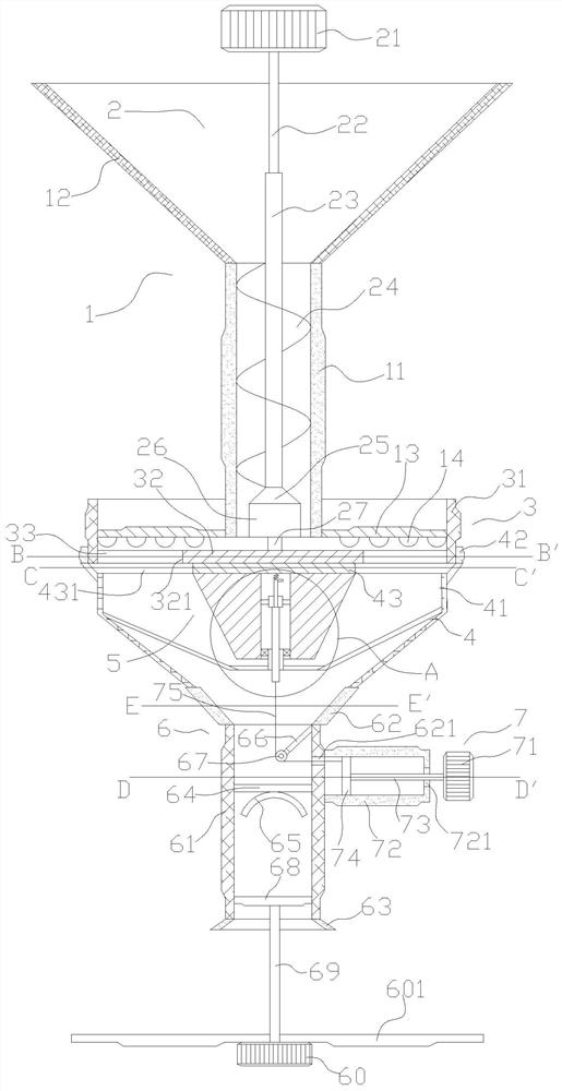
[0035] Such as figure 1 As shown, the construction waste recovery treatment device of the present invention includes a feeding structure 1, a rotating structure 2 arranged on the feeding structure 1, a centralized structure 3 arranged below the feeding structure 1, and a 3, the connecting structure 4 below, the screening structure 5 arranged in the connecting structure 4, the pressing block structure 6 located below the connecting structure 4, and the piston structure 7 arranged on the pressing block structure 6.

[0036] Wherein, the feed structure 1 includes a feed frame 11, a feed hopper 12 arranged above the feed frame 11, the feed frame 11 is preferably a hollow cylinder and the upper and lower surfaces communicate; The hopper 12 is preferably a hollow conical body with a wide top and a narrow bottom. The lower surface of the feed hopper 12 is fixedly connected to the upper surface of the feed frame 11, and the inside of the feed hopper 12 is connected to the feed frame. ...

Embodiment 2

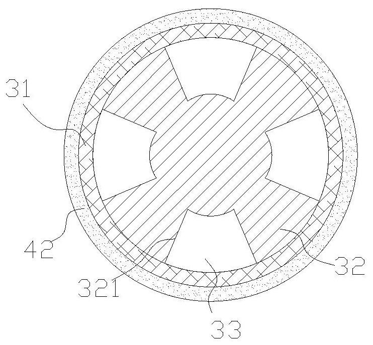
[0040] Such as figure 1 and image 3 As shown, the centralization structure 3 includes a centralization frame 31 , a support plate 32 fixedly connected within the centralization frame 31 , and a plurality of first filter screens 33 disposed on the support plate 32 . The centralizing frame 31 is a hollow cylinder with the upper and lower surfaces connected. The support plate 32 is a circular plate with several through holes on the side, the lower end of the connecting rod 27 is fixedly connected to the center of the support plate 32, and the support plate 32 is provided with a first through hole 321 at its edge. , the number is several and evenly distributed in the circumferential direction. The number of the first filter screen 33 is the same as the number of the first through holes 321, the first filter screen 33 is accommodated in the first through hole 321 and fixedly connected with the support plate 32, the The first filter screen 33 can filter the crushed and ground mu...

Embodiment 3

[0043] A pressing plate 13 is fixedly arranged at the lower end of the feeding frame 11. The pressing plate is a disc-shaped structure whose center is the feeding frame. connection, to realize that the pressing plate and the centralized frame can rotate relatively horizontally, and the vertical direction is limited by the installation groove and will not move; there are several first grinding blocks 14 fixedly connected under the pressing plate 13; Relative movement, that is, relative rotation, so that the waste materials between the support plate 32 , the first filter screen 33 and the pressing plate 13 can be fully pulverized, and the pulverization effect is remarkable.

[0044] All the other are identical with embodiment 2.

[0045] The setting of the feeding structure 1 is convenient for feeding, that is, the user can put the dregs and the like into the feeding hopper 12, which is easy to operate and convenient to use, and the dregs can enter the feeding frame under the ac...


PUM


Abstract

The invention relates to the technical field of construction machinery, in particular to a construction waste recycling device. The device comprises a feeding structure, a rotating structure arrangedon the feeding structure, a concentrating structure arranged below the feeding structure, a connecting structure arranged below the concentrating structure and a screening structure arranged in the connecting structure; the feeding structure comprises a feeding frame; and the rotating structure comprises a motor, a first rotating shaft arranged on the motor, a second rotating shaft arranged at thelower end of the first rotating shaft, a spiral cutter arranged on the second rotating shaft, a connecting block arranged at the lower end of the second rotating shaft and a second grinding block arranged on the connecting block. According to the device, the operation is simple and convenient, muck is fully crushed and is not prone to blocking a screen, and the treatment efficiency is high.

Description

technical field [0001] The invention relates to the technical field of construction machinery, in particular to a recycling and processing device for construction waste. Background technique [0002] With the acceleration of urbanization and the expansion of scale, construction projects are gradually increasing, and there are more and more construction waste such as muck, so it is necessary to recycle construction waste. Existing slag treatment devices mainly process the slag by crushing and screening, and then recycle it. However, the existing crushing and screening processes often use independent equipment, that is, crushing and screening are carried out separately. This method leads to The process is cumbersome and the operation is not simple enough to significantly improve the efficiency of muck treatment; and because the crushing of muck is not sufficient enough, it is easy to be blocked during screening, which affects the smooth progress of its treatment, and even lead...

Claims


Application Information

Patent Timeline
Patent Type & Authority Applications(China)
IPC IPC(8): B02C18/10B02C2/10B02C23/14B07B1/55B30B9/30
CPCB02C2/10B02C18/0092B02C18/10B02C23/14B07B1/55B30B9/3003B30B9/306
Inventor 部德芳
Owner 部德芳
Why Eureka
Try Eureka