Supercharge Your Innovation With Domain-Expert AI Agents!

Transmission device of tool bit angle-adjustable electric screwdriver

An electric screwdriver and transmission technology, applied in the field of mechanical parts, can solve the problems that the blade cannot fully enter, the screwdriver cannot transmit torque, the screwdriver cannot work, etc., and achieves the effects of strong promotion value, compact structure, and convenient installation and maintenance.

Active Publication Date: 2017-02-22
重庆前进焊接材料制造有限公司
View PDF5 Cites 0 Cited by
  • Summary
  • Abstract
  • Description
  • Claims
  • Application Information

AI Technical Summary

Problems solved by technology

[0003] Now, in order to reduce labor intensity, electric screwdrivers are becoming more and more popular. However, like ordinary manual screwdrivers, when there is a foreign object blocking the top of the screw groove, the edge of the screwdriver cannot fully enter the screw groove. The screwdriver cannot transmit torque to the screw, the screwdriver does not work

Method used


Image

  • Transmission device of tool bit angle-adjustable electric screwdriver
  • Transmission device of tool bit angle-adjustable electric screwdriver
  • Transmission device of tool bit angle-adjustable electric screwdriver

Examples


Embodiment 1

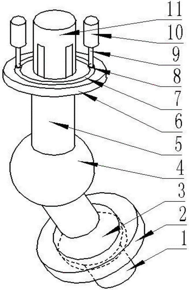
[0028] Such as figure 1 As shown in -5, in order to overcome the defects of the prior art, the present invention provides a transmission device of an electric screwdriver with an adjustable cutter head angle, which includes a ring column 2, a cardan shaft 4, a driven shaft 5 and a driving shaft 11. A sliding groove 14 is provided on the side of the driving shaft 11. The sliding groove 14 is parallel to the axis of the driving shaft 11. The sliding groove 14 penetrates from the middle of the driving shaft 11 to the free end of the driving shaft 11. A sliding plate 12 is installed in the sliding groove 11. The sliding plate 12 is installed on one end of the driven shaft 5, the driven shaft 5 is fixedly equipped with a turntable 6, the driven shaft 5 passes through the middle part of the turntable 6 vertically, the turntable 6 is provided with a round groove 7, and the round groove 7 is equipped with a second Two spheres 8, the second sphere 8 is connected with the piston rod 9, ...

Embodiment 2

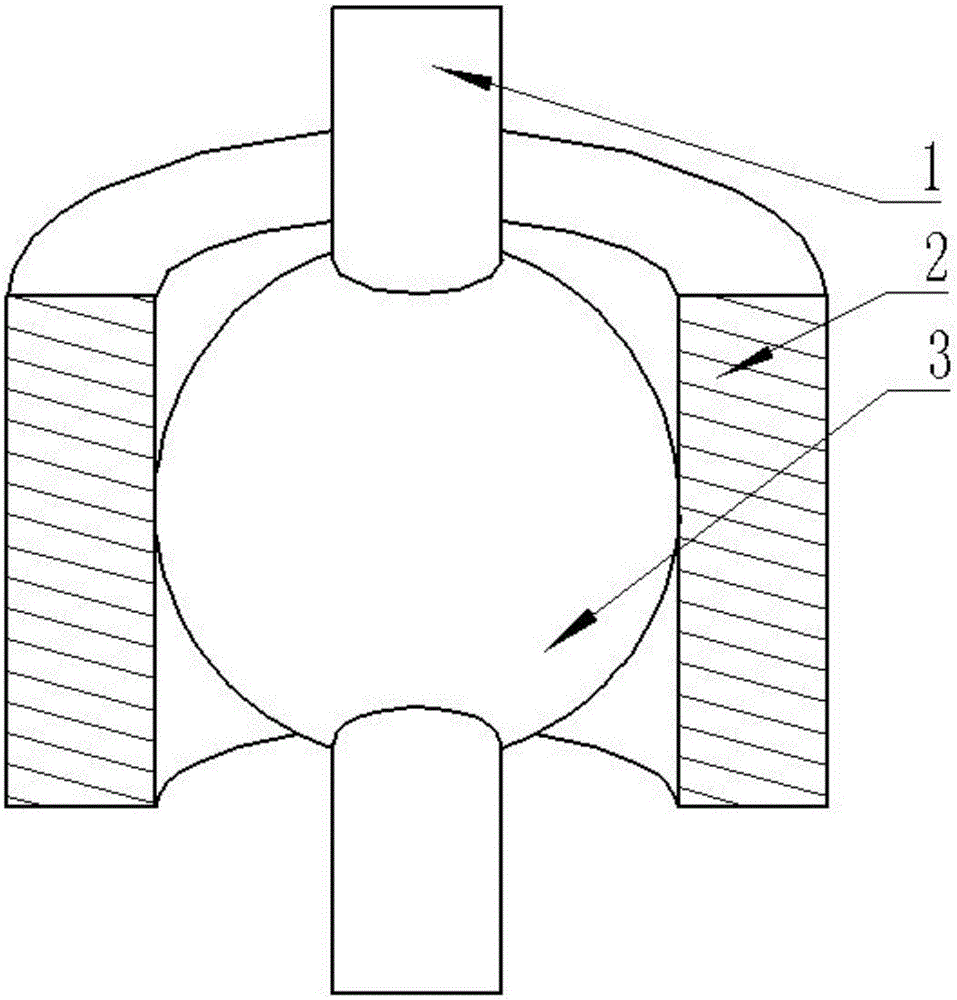
[0034] This embodiment is further improved on the basis of embodiment 1, as figure 1 As shown in -5, in order to realize that the driving shaft 11 drives the driven shaft 5 and the rotating shaft 1 to rotate, the angle between the driven shaft 5 and the rotating shaft 1 is variable, and the axis of the driving shaft 11 is collinear with the axis of the driven shaft 5; The axis of the shaft 5 intersects the axis of the rotating shaft 1 .

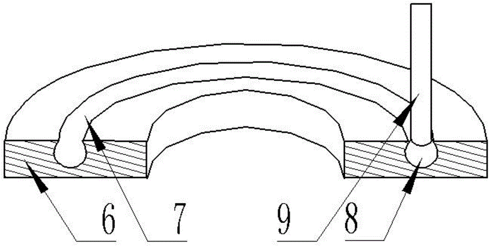
[0035] The cross-section of the circular groove 7 is an arc, the diameter of which is the same as that of the second sphere 8, the depth of the circular groove 7 is greater than the diameter of the second sphere 8, and the length of the line connecting the two ends of the arc is greater than the diameter of the piston rod 9. This setting enables the piston rod 9 to control the expansion and contraction of the turntable 6, but the piston rod 9 does not affect the rotation of the turntable 6.

[0036] The inner diameter of the ring column 2 is...


PUM


Abstract

The invention discloses a transmission device of a tool bit angle-adjustable electric screwdriver. The transmission device comprises a cylindrical column, an universal shaft, a driven shaft and a driving shaft; a chute is formed in the side surface of the driving shaft, and is parallel to the axis of the driving shaft; the chute penetrates from the middle part of the driving shaft to a free end of the driving shaft; a slide plate is mounted in the chute, and is mounted at one end of the driven shaft; a turntable is fixedly mounted on the driven shaft; the driven shaft vertically penetrates through the middle part of the turntable; a circular groove is formed in the turntable; a second ball body is mounted in the circular groove, and is connected with a piston rod; the piston rod is connected with a hydraulic cylinder; the other end of the driven shaft is connected with a rotating shaft through an universal shaft; a first ball body is fixedly mounted on the rotating shaft; the axis of the rotating shaft penetrates through the ball center of the first ball body; and the first ball body is mounted in the cylindrical column. The transmission device is adjustable in tool bit angle of the electric screwdriver, can enable the electric screwdriver to work under abnormal working conditions, and is convenient and practical.

Description

technical field [0001] The invention relates to the technical field of mechanical parts, in particular to a transmission device for an electric screwdriver with an adjustable blade angle. Background technique [0002] When the screwdriver is used to screw the screw, the working principle of the wheel shaft is used. In order to apply a small torque to the flat-blade screw, people think of opening a slot on the screw head, and the corresponding flat-blade screwdriver can be conveniently tightened and loosened. Screws, but with the rapid development of science and technology, the application of screws is more and more extensive, and the shortcomings of screws and flat-blade screwdrivers have also emerged. First of all, once the slot of the screw head is damaged, the screw cannot be unscrewed. The longer the length of the slot, the easier it is to be damaged during the screwing process. In order to shorten the length of the notch, improve the ability of the notch to resist dam...

Claims


Application Information

Patent Timeline
Patent Type & Authority Applications(China)
IPC IPC(8): B25B23/00
CPCB25B23/0028
Inventor 温晓琳
Owner 重庆前进焊接材料制造有限公司
Features
  • R&D
  • Intellectual Property
  • Life Sciences
  • Materials
  • Tech Scout
  • Unparalleled Data Quality
  • Higher Quality Content
  • 60% Fewer Hallucinations
Learn More