Method and device for detaching piston relieving spring of locomotive brake cylinder

A technology for relieving springs and brake cylinders, applied in the field of locomotive brake system maintenance, can solve problems such as potential safety hazards, long time consumption, and high labor intensity of employees

Active Publication Date: 2017-02-22
SHANDONG IRON & STEEL CO LTD
View PDF8 Cites 2 Cited by
  • Summary
  • Abstract
  • Description
  • Claims
  • Application Information

AI Technical Summary

Problems solved by technology

This disassembly method takes a long time, the labor intensity of the employees is high, and there is a safety hazard of the spring collapsing during the operation
[0003] To sum up, how to solve the proble

Method used


Image

  • Method and device for detaching piston relieving spring of locomotive brake cylinder
  • Method and device for detaching piston relieving spring of locomotive brake cylinder

Examples


Embodiment Construction

[0030] The core of the present invention is to provide a method and device for dismounting the brake cylinder relieving spring of a locomotive, so as to reduce the labor intensity of operators and avoid potential safety hazards at the same time.

[0031] In order to enable those skilled in the art to better understand the technical solutions provided by the present invention, the present invention will be further described in detail below in conjunction with the accompanying drawings and specific embodiments.

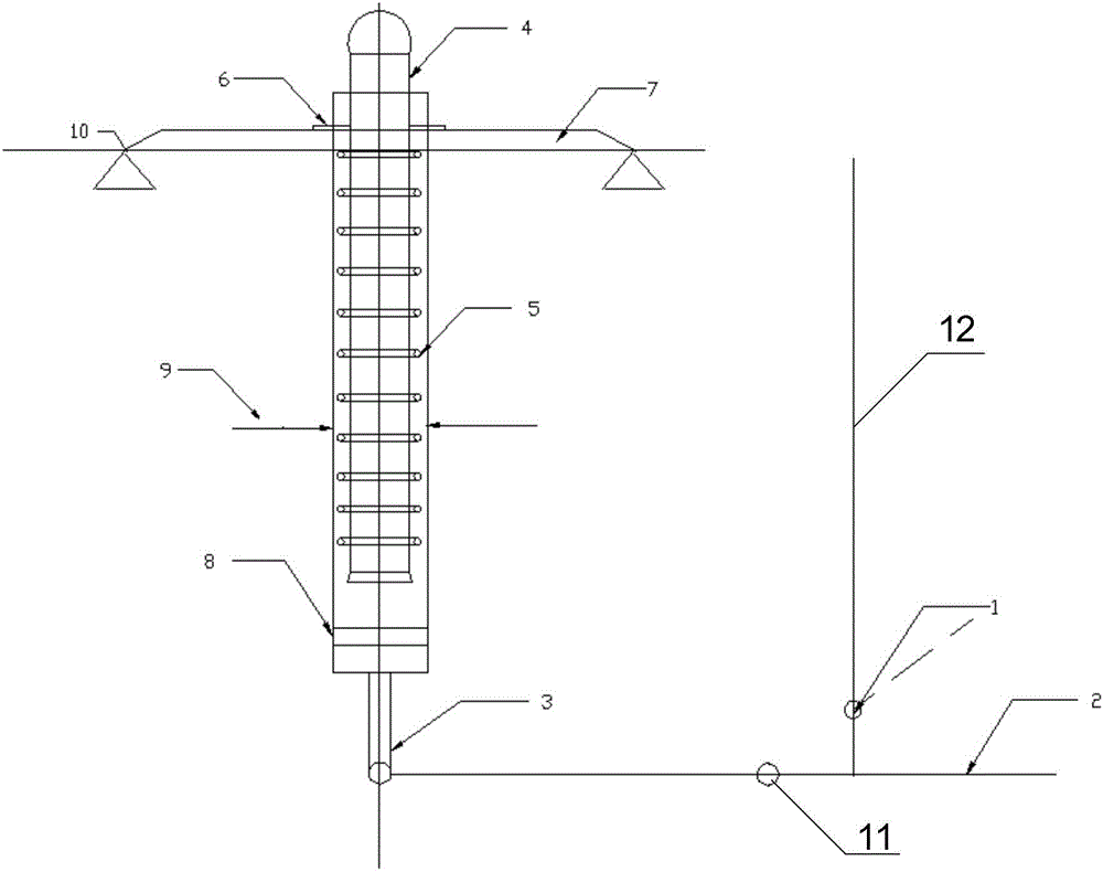
[0032] like figure 1 As shown, the embodiment of the present invention provides a device for dismounting the brake cylinder of a locomotive to relieve the spring, including:

[0033] A positioning device 10 for fixing the brake cylinder head 7;

[0034] A push rod 3 for pushing the relief spring 5 to perform a compression movement, the push rod 3 includes a first end and a second end, and the first end is used to push the screw 4 inside the relief spring 5 to move;

...


PUM

PropertyMeasurementUnit
Sizeaaaaaaaaaa

Abstract

The invention discloses a device for detaching a piston relieving spring of a locomotive brake cylinder. The device comprises a positioning device, a pushing rod and a lever, wherein the positioning device is used for fixing a brake cylinder cover; the pushing rod is used for driving a relieving spring to compress; the pushing rod comprises a first end part and a second end part; the first end part is used for driving a screw rod on the inner side of the relieving spring to move; the lever is used for driving the pushing rod to move; one end of the lever is arranged as a hinge end; the other end of the lever is arranged as a moveable free end; the hinge end is hinged with the second end part; a locking mechanism is connected with the free end. The device can reduce the labor intensity of the operator and can avoid potential safety hazard. Besides, the invention also discloses a method for detaching the piston relieving spring of the locomotive brake cylinder.

Description

technical field [0001] The invention relates to the technical field of maintenance of a locomotive brake system, in particular to a method and a device for removing a spring of a brake cylinder of a locomotive. Background technique [0002] When the brake unit of a locomotive is disassembled for inspection and replacement of the relief spring of the brake cylinder (piston), due to the large diameter, strong stiffness, and high elasticity of the spring, the danger of the spring collapsing and hurting people is very likely to occur during the disassembly inspection. The conventional disassembly method is: the brake cylinder block is fixed manually, the brake cylinder cover is pressed manually, and then the pin that fixes the assembly is taken out with a pin remover, and the release spring of the brake is taken out. In the specific operation process, the direction of the applied force is downward, and the relieving spring is compressed downwards with artificial force, so as to ...

Claims


Application Information

Patent Timeline
IPC IPC(8): B25B27/00
CPCB25B27/0035
Inventor 朱颖珍韩树森段崇义邵学陈兴
Owner SHANDONG IRON & STEEL CO LTD
Why Eureka
Try Eureka