

Electric power tool cabinet
A technology of power tools and outer frames, applied in the field of power tool cabinets, can solve the problems of lack of convenient functions, poor structural stability, short service life, etc., and achieve the effects of convenient installation, weight reduction, and easy transportation
- Summary
- Abstract
- Description
- Claims
- Application Information
AI Technical Summary
Problems solved by technology
Method used
Image

Examples
Embodiment 1
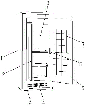
[0023] Such as figure 1 As shown, a power tool cabinet includes an outer frame 1, a baffle 2 and a partition 3, the baffle 2 is arranged in the outer frame 1, the baffle 2 is welded to the outer frame 1, and the baffle 2 is Vertically arranged, the partition 3 is arranged on one side of the baffle 2, the partition 3 is welded with the baffle 2, and more than one partition 3 is provided, and the bottom of the outer frame 1 is provided with a cooling hole 4, so One side of the outer frame 1 is provided with a mounting hole 5 and a door panel 6, the door panel 6 is hinged with the outer frame 1 through the mounting hole 5, and the outer frame 1 is provided with a reinforcing rib 7, and the reinforcing rib 7 is provided with more than one , the reinforcing ribs 7 are arranged in a criss-cross pattern, and the reinforcing ribs 7 are welded to the door panel 6 .
[0024] The distance between the partitions 3 is 50 cm.
[0025] More than one cooling hole 4 is provided.
[0026] A ...
Embodiment 2
[0037] Such as figure 1 As shown, a power tool cabinet includes an outer frame 1, a baffle 2 and a partition 3, the baffle 2 is arranged in the outer frame 1, the baffle 2 is welded to the outer frame 1, and the baffle 2 is Vertically arranged, the partition 3 is arranged on one side of the baffle 2, the partition 3 is welded with the baffle 2, and more than one partition 3 is provided, and the bottom of the outer frame 1 is provided with a cooling hole 4, so One side of the outer frame 1 is provided with a mounting hole 5 and a door panel 6, the door panel 6 is hinged with the outer frame 1 through the mounting hole 5, and the outer frame 1 is provided with a reinforcing rib 7, and the reinforcing rib 7 is provided with more than one , the reinforcing ribs 7 are arranged in a criss-cross pattern, and the reinforcing ribs 7 are welded to the door panel 6 .
[0038] The distance between the partitions 3 is 50 cm.
[0039] More than one cooling hole 4 is provided.
[0040] A ...
Embodiment 3
[0051] Such as figure 1 As shown, a power tool cabinet includes an outer frame 1, a baffle 2 and a partition 3, the baffle 2 is arranged in the outer frame 1, the baffle 2 is welded to the outer frame 1, and the baffle 2 is Vertically arranged, the partition 3 is arranged on one side of the baffle 2, the partition 3 is welded with the baffle 2, and more than one partition 3 is provided, and the bottom of the outer frame 1 is provided with a cooling hole 4, so One side of the outer frame 1 is provided with a mounting hole 5 and a door panel 6, the door panel 6 is hinged with the outer frame 1 through the mounting hole 5, and the outer frame 1 is provided with a reinforcing rib 7, and the reinforcing rib 7 is provided with more than one , the reinforcing ribs 7 are arranged in a criss-cross pattern, and the reinforcing ribs 7 are welded to the door panel 6 .
[0052] The distance between the partitions 3 is 50 cm.
[0053] More than one cooling hole 4 is provided.
[0054] A ...
PUM
| Property | Measurement | Unit |
|---|---|---|
| thickness | aaaaa | aaaaa |
| length | aaaaa | aaaaa |
| thickness | aaaaa | aaaaa |
Abstract
Description
Claims
Application Information