
A large-scale hot runner system in which glue leakage does not interfere with the operation of the system

A technology of interference system and hot runner, which is applied in the field of large hot runner system, can solve problems such as mold damage, mold wear, hot runner system cannot operate normally, and achieve the effect of ensuring normal operation and eliminating mold wear

Active Publication Date: 2019-05-24
东莞市热恒注塑科技有限公司
View PDF12 Cites 0 Cited by
  • Summary
  • Abstract
  • Description
  • Claims
  • Application Information

AI Technical Summary

Problems solved by technology

[0003] For the current large-scale hot runner system, hot runner glue leakage is the main factor causing mold wear and shutdown, and the hot runner system's glue leakage-prone area generally occurs at the joint of two adjacent manifolds, where glue leakage Finally, the plastic melt will continue to seep into the two adjacent manifolds, and then the entire hot runner system will be filled with plastic, which will eventually cause the entire hot runner system to fail to operate normally, greatly increasing the mold repair cost
In addition, glue leakage in the hot runner system is difficult to eliminate. The improvements people have made so far are to strengthen the seal to reduce the amount of glue leakage and the places where the glue leaks. However, this makes the structure of the hot runner system more complicated and the cost increases. little effect
[0004] In addition, in the existing large-scale hot runner system, due to the small distance between two adjacent manifolds, the heat radiated by the two manifolds will make the temperature of the mold too high, which will cause damage to the mold, and Not easy to set up the cooling system due to the small spacing
Also because the distance between adjacent splitter plates is small, it is impossible for the driving device that drives the valve needle to be installed on the spacer, and the installation position of the driving device should avoid the splitter plate above it, so that The driving device should be installed above all the diverter plates, which makes the length of the valve needle must be long enough, which not only increases the material cost, but also makes the valve needle easy to bend and deform, which affects the service life of the mold

Method used


Image

  • A large-scale hot runner system in which glue leakage does not interfere with the operation of the system
  • A large-scale hot runner system in which glue leakage does not interfere with the operation of the system

Examples


Embodiment Construction

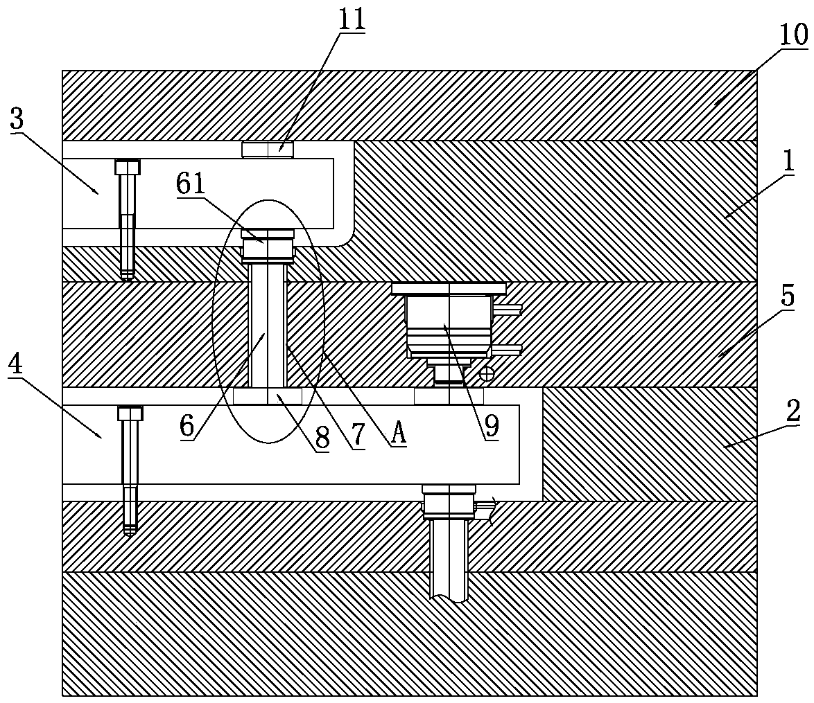
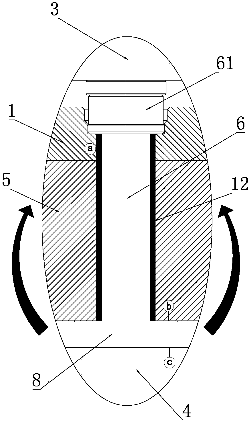
[0035] The present invention will be further described in conjunction with the following examples, a large-scale hot runner system of the present invention that does not interfere with the operation of the system, such as figure 1 and figure 2 As shown, its structure includes a first template 1 and a second template 2, the first template 1 is embedded with a first splitter plate 3 fixed to it, and the second template 2 is embedded with a second splitter plate 4 fixed to it, A transition template is provided between the first splitter plate 3 and the second splitter plate 4. In this embodiment, the transition template includes a third template 5 and a part of the first template 1 tightly pressed with the third template 5. The third template 5 is arranged between the first template 1 and the second template 2, of course, the transition template can also be an independent third template 5.

[0036] The transition template is provided with a through hole, and a transition hot no...


PUM


Abstract

The invention relates to the technical field of hot runners, in particular to a large hot runner system without interfering system operation after glue leakage. The large hot runner system structurally comprises a transition template arranged between a first spreader plate and a second spreader plate; the transition template is provided with a through hole; a transition hot sprue is arranged in the through hole; an inlet end face of the transition hot sprue pushes against the first spreader plate; an outlet end face of the transition hot sprue pushes against the second spreader plate; and a gap between the outer wall of the transition hot sprue and the inner wall of the through hole is bigger than a gap between the periphery part of an opening of the through hole of the transition template and the first spreader plate, and a gap between the periphery part of the opening of the through hole of the transition template and the second spreader plate. In this way, molten glue leaking from the transition hot sprue shall flow into and is collected in the gap between the outer wall of the transition hot sprue and the inner wall of the through hole, and can not leak outwards continuously to flow onto the first spreader plate or the second spreader plate. Therefore, even if the large hot runner system has the glue leakage, normal operation of the overall large hot runner system can be guaranteed, and die wear arising from the glue leakage can be eliminated.

Description

technical field [0001] The invention relates to the technical field of hot runners, in particular to a large-scale hot runner system with complementary interference of glue leakage. Background technique [0002] Large-scale hot runner systems are generally equipped with multi-layer manifolds. These manifolds are the central components of the hot runner system. The manifolds can not only make the flow rate of the plastic melt more stable, but also make the cavity of the mold more uniform and fully filled. . During the injection molding process, the plastic melt flowing out of the main channel flows sequentially through each manifold in each layer of distributor plates, diverts and transfers to each hot nozzle, and finally flows into the cavity of the mold through the hot nozzle. [0003] For the current large-scale hot runner system, hot runner glue leakage is the main factor causing mold wear and shutdown, and the hot runner system's glue leakage-prone area generally occurs...

Claims


Application Information

Patent Timeline
Patent Type & Authority Patents(China)
IPC IPC(8): B29C45/27B29C45/73
CPCB29C45/27B29C45/73
Inventor 阮军平
Owner 东莞市热恒注塑科技有限公司
Learn More